System Sensor M500DR Manual

File Preview
Click below to download for free
Click below to download for free
File Data
| Name | system-sensor-m500dr-manual-2350864197.pdf |
|---|---|
| Type | |
| Size | 800.70 KB |
| Downloads |
Text Preview
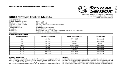
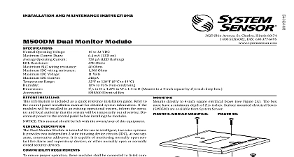
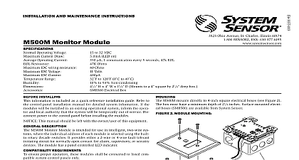
I 3825 Ohio Avenue St Charles Illinois 60174 FAX 630 377 6495 AND MAINTENANCE INSTRUCTIONS Audio Control Module Operating Voltage Current Draw Operating Current Supply Voltage Maximum between Terminals T2 T3 or T4 T5 70.7 Volts RMS 50W Range to 32 VDC mA LED on LED flashing Installing information is included as a quick reference instal guide Refer to the control panel installation man for detailed system information If the modules will installed in an existing operational system inform the and local authority that the system will be tempo out of service Disconnect power to the control panel installing the modules This manual should be left with the owner user this equipment Description Audio Control Modules are intended for use in in two wire systems where the individual address of module is selected using the built in rotary switches module is used to select either one of two separate au signals then connect it to a speaker circuit Wiring to the circuit is supervised and status is reported to the as NORMAL OPEN or SHORT CIRCUIT The M500DR two pairs of output termination points available for fault wiring and does not require external non polarized There is a panel controlled LED indicator Requirements ensure proper operation this module shall be connected compatible system control panels only module mounts directly to 4 square electrical boxes see 2A The box must have a minimum depth of 21 8 mounted electrical boxes SMB500 are available All wiring must conform to applicable local codes and regulations When using control modules nonpower limited applications the CB500 Module Bar must be used to meet UL requirements for the separa of power limited and nonpower limited terminals and The barrier must be inserted into a 4 4 21 8 box and the control module must be placed into barrier and attached to the junction box Figure 2A to 120 0 to 49 to 93 Non condensing H x 4 W x 11 4 D Mounts to a 4 square by 21 8 deep box Electrical Box CB500 Barrier power limited wiring must be placed into the isolated of the module barrier Figure 2B Install module wiring in accordance with the job draw and appropriate wiring diagrams Figures 3 4 Set the address on the module per job drawings Secure module to electrical box supplied by installer shown in Figure 2A 1 Controls Indicators 2A Module with 865 6 7 8 9 2B Isolated Quadrant 3 Typical wiring for speaker supervision and switching NFPA Style Y WIRING SHOWN IS SUPERVISED NEXT LINE CIRCUIT SLC VDC MAX PAIR RECOMMENDED MODULES TO LISTED COMPATIBLE PANELS ONLY PANEL OR DEVICE CIRCUITS NOT LOOP WIRE AROUND TERMINALS WIRE TO ENSURE OF CONNECTIONS AMPLIFIER B Vrms MAX AMPLIFIER A Vrms MAX 6 7 8 9 6 7 8 9 K EOL POLARITIES ARE IN ALARM NEXT MODULE MODULE MUST RETURN FOR SUPERVISION CIRCUIT WIRING MUST BE TWISTED PAIR AS A MINIMUM A 70.7V AUDIO AMPLIFIER IS USED TERMINALS 0 AND 1 ARE POWER LIMITED TERMINALS 2 9 ARE NONPOWER LIMITED IN THIS CASE THE CB500 BARRIER REQUIRED OTHERWISE ALL TERMINAL WIRING IS POWER LIMITED THE CB500 A LABEL INDICATING WHICH TERMINALS ARE NONPOWER LIMITED LABEL MUST BE PLACED ADJACENT TO THE NAMEPLATE LABEL ON THE MODULE HOUSING 4 Typical wiring for speaker supervision and switching NFPA Style Z WIRING SHOWN IS SUPERVISED NEXT LINE CIRCUIT SLC VDC MAX PAIR RECOMMENDED RESISTOR INTERNAL AT 8 9 POLARITIES ARE IN ALARM 6 7 8 9 6 7 8 9 MODULES TO LISTED COMPATIBLE PANELS ONLY PANEL OR DEVICE CIRCUITS NOT LOOP WIRE AROUND TERMINALS WIRE TO ENSURE OF CONNECTIONS AMPLIFIER B Vrms MAX AMPLIFIER A Vrms MAX NEXT MODULE MODULE MUST RETURN FOR SUPERVISION CIRCUIT WIRING MUST BE TWISTED PAIR AS A MINIMUM A 70.7V AUDIO AMPLIFIER IS USED TERMINALS 0 AND 1 ARE POWER LIMITED TERMINALS 2 9 ARE NONPOWER LIMITED IN THIS CASE THE CB500 BARRIER REQUIRED OTHERWISE ALL TERMINAL WIRING IS POWER LIMITED THE CB500 A LABEL INDICATING WHICH TERMINALS ARE NONPOWER LIMITED LABEL MUST BE PLACED ADJACENT TO THE NAMEPLATE LABEL ON THE MODULE HOUSING relay switch contacts are shipped in the standby state open state but may have transferred to the activated closed during shipping To ensure that the switch contacts are in their correct state modules must be made to communicate the panel before connecting circuits controlled by the module Limited Warranty Sensor warrants its enclosed product to be free from defects in materi and workmanship under normal use and service for a period of three years date of manufacture System Sensor makes no other express warranty the enclosed product No agent representative dealer or employee of the has the authority to increase or alter the obligations or limitations this Warranty The Company obligation of this Warranty shall be limited the replacement of any part of the product which is found to be defective materials or workmanship under normal use and service during the three period commencing with the date of manufacture After phoning System toll free number 800 SENSOR2 736 7672 for a Return Authorization send defective units postage prepaid to System Sensor Returns RA 3825 Ohio Avenue St Charles IL 60174 Please a note describing the malfunction and suspected cause of failure Company shall not be obligated to replace units which are found to be because of damage unreasonable use modifications or alterations after the date of manufacture In no case shall the Company be for any consequential or incidental damages for breach of this or any Warranty expressed or implied whatsoever even if the loss or damage caused by the Company negligence or fault Some states do not allow the or limitation of incidental or consequential damages so the above or exclusion may not apply to you This Warranty gives you specific rights and you may also have other rights which vary from state to state Sensor 2006