System Sensor M500S Manual

File Preview
Click below to download for free
Click below to download for free
File Data
| Name | system-sensor-m500s-manual-8921345607.pdf |
|---|---|
| Type | |
| Size | 1.75 MB |
| Downloads |
Text Preview
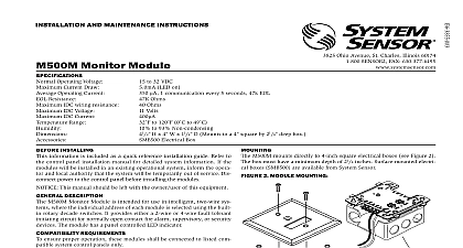
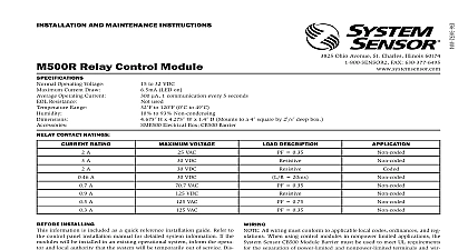
INSTALLATION AND MAINTENANCE INSTRUCTIONS Ohio Avenue Illinois 60174 FAX 630 377 6495 Supervised Control Module Operating Voltage Current Draw Current NAC Line Loss Supply Voltage between Terminals T10 and T11 NAC Current Ratings Range to 32 VDC LED On max 1 communication every 5 seconds 47k EOL resistor 485 max Communicating NAC Shorted VDC 24VDC NAC Speakers 70.07 V RMS 50 W class B wiring system the current rating is 3A For class A wiring system the current rating is 2A to 120 0 to 49 to 93 Non condensing 4.675 H x 4.275 W x 1.4 D Mounts to a 4 square by 21 8 deep box Electrical Box CB500 Barrier CONTACT RATINGS RATING VOLTAGE DESCRIPTION A A A A A A A A VAC VDC VDC VDC VAC VDC VAC VAC 20ms 0.35 0.35 0.75 0.35 M500S mounts directly to 4 inch square electrical boxes see Figure 2A box must have a minimum depth of 21 8 inches Surface mounted electri boxes SMB500 are available from System Sensor The module can also to the DNR W duct housing 1 CONTROLS AND INDICATORS INSTALLING information is included as a quick reference installation guide Refer to control panel installation manual for detailed system information If the will be installed in an existing operational system inform the opera and local authority that the system will be temporarily out of service Dis power to the control panel before installing the modules This manual should be left with the owner user of this equipment DESCRIPTION Supervised Control Modules are intended for use in intelligent two systems where the individual address of each module is selected using built in rotary decade switches This module is used to switch an external supply which can be a DC power supply or an audio amplifier up 80 VRMS to notification appliances It also supervises the wiring to the loads and reports their status to the panel as NORMAL OPEN SHORT CIRCUIT The M500S has two pairs of output termination points for fault tolerant wiring and a panel controlled LED indicator This can be used to replace an M500C module that has been configured for wiring operation REQUIREMENTS ensure proper operation these modules shall be connected to listed com system control panels only 2A MODULE MOUNTING FIGURE 2B BARRIER All wiring must conform to applicable local codes ordinances and reg When using control modules in nonpower limited applications the Sensor CB500 Module Barrier must be used to meet UL requirements the separation of power limited and nonpower limited terminals and wir The barrier must be inserted into a 4 junction box and the module must be placed into the barrier and attached to the junction Figure 2A The power limited wiring must be placed into the isolated of the module barrier Figure 2B Install module wiring in accordance with the job drawings and appropri wiring diagrams the address on the module per job drawings Secure module to electrical box supplied by installer as shown in 2A should be stripped to the appropriate length recommended strip length 1 4 to 3 8 Exposed conductor should be secured under the clamping plate should not protrude beyond the terminal block area Caution Do not loop under terminals Break wire run to provide supervision of connections All references to power limited represent Limited Class 2 references to Class A also include Class X 3 TYPICAL NOTIFICATION APPLIANCE CIRCUIT CONFIGURATION NFPA STYLE Y NOT LOOP WIRE ON TERMINALS 10 11 BREAK WIRE TO PROVIDE SUPERVISION OF CONNECTIONS VDC CIRCUIT MODULES TO COMPATIBLE PANELS ONLY VDC POWER SUPPLY REGULATED LIMITED PER NFPA 70 FOR FIRE PROTECTION BATTERY BACKUP POLARITIES ARE IN ALARM EOL LISTED EOL RELAY ENERGIZED VDC COIL EOLR 1 NEXT CONTROL MODULE OR END OF LINE ONE RELAY REQUIRED FOR EACH SOME CONTROL PANELS HAVE RELAY IN AND DO NOT REQUIRE EXTERNAL REFER TO PANEL MANUAL OR LINE CIRCUIT SLC VDC MAX PAIR RECOMMENDED WIRING SHOWN IS SUPERVISED POWER LIMITED NEXT ANY FAULT IN THE POWER SUPPLY IS TO THAT ZONE AND DOES NOT IN A FAULT IN A SEPARATE ZONE 4 TYPICAL FAULT TOLERANT NOTIFICATION APPLIANCE CIRCUIT CONFIGURATION NFPA STYLE Z VDC POWER SUPPLY REGULATED POWER PER NFPA 70 LISTED FIRE PROTECTION WITH BACKUP VDC CIRCUIT NOT LOOP WIRE ON TERMINALS 10 11 WIRE RUN TO PROVIDE SUPERVISION CONNECTIONS MODULES TO LISTED CONTROL PANELS ONLY OR POLARITIES ARE IN ALARM RESISTOR INTERNAL AT 9 LISTED EOL SHOWN VDC COIL NEXT CONTROL MODULE OR RELAY ONE RELAY FOR EACH CIRCUIT CONTROL PANELS HAVE BUILT IN AND DO NOT EXTERNAL WIRING TO PANEL MANUAL LINE CIRCUIT SLC VDC MAX TWISTED PAIR RECOMMENDED WIRING SHOWN IS SUPERVISED POWER LIMITED ANY FAULT IN THE POWER SUPPLY LIMITED TO THAT ZONE AND DOES NOT IN A FAULT IN A SEPARATE ZONE 5 TYPICAL WIRING FOR SPEAKER SUPERVISION AND SWITCHING NFPA STYLE Y CIRCUIT WIRING MUST BE TWISTED PAIR AS A MINIMUM SEE PANEL INSTALLATION MANUAL FOR DETAILED INFORMATION MUST BE PER NFPA MODULES TO LISTED COMPATIBLE PANELS ONLY PANEL OR DEVICE LINE CIRCUIT SLC VDC MAX PAIR RECOMMENDED CIRCUIT NOT LOOP WIRE AROUND TERMINALS 11 BREAK WIRE TO ENSURE OF CONNECTIONS AMPLIFIER 70.7 Vrms MAX MUST PROVIDE WIRING PER NFPA EOL POLARITIES ARE IN ALARM NEXT CONTROL MODULE MODULE MUST RETURN FOR SUPERVISION MUST BE LISTED FOR FIRE PROTECTION ANY FAULT IN THE POWER SUPPLY IS LIMITED TO THAT ZONE AND DOES NOT RESULT IN A FAULT IN A SEPARATE ZONE NEXT 6 TYPICAL FAULT TOLERANT WIRING FOR SPEAKER SUPERVISION AND SWITCHING NFPA STYLE Z CIRCUIT WIRING MUST BE TWISTED PAIR AS A MINIMUM SEE PANEL INSTALLATION MANUAL FOR DETAILED INFORMATION MODULES TO LISTED COMPATIBLE CONTROL PANELS ONLY CIRCUIT NOT LOOP WIRE AROUND TERMINALS 11 BREAK WIRE TO ENSURE OF CONNECTIONS AMPLIFIER 70.7 Vrms MAX MUST PROVIDE WIRING PER NFPA MUST BE PER NFPA EOL RESISTOR INTERNAL AT 8 9 CAPACITORS 100 NONPOLARIZED LEAKAGE POLARITIES ARE IN ALARM NEXT CONTROL MODULE MODULE MUST RETURN FOR SUPERVISION MUST BE LISTED FOR PROTECTION ANY FAULT IN THE POWER SUPPLY IS LIMITED TO THAT ZONE AND DOES NOT RESULT IN A FAULT IN A SEPARATE ZONE OR LINE CIRCUIT SLC VDC MAX PAIR RECOMMENDED WIRING SHOWN IS SUPERVISED POWER LIMITED NEXT LIMITED WARRANTY relay switch contacts are shipped in the standby state open state but may