System Sensor m502m-installation

File Preview
Click below to download for free
Click below to download for free
File Data
| Name | system-sensor-m502m-installation-8621935047.pdf |
|---|---|
| Type | |
| Size | 645.06 KB |
| Downloads |
Text Preview
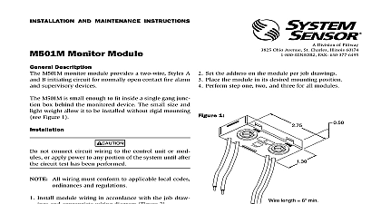
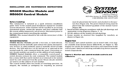
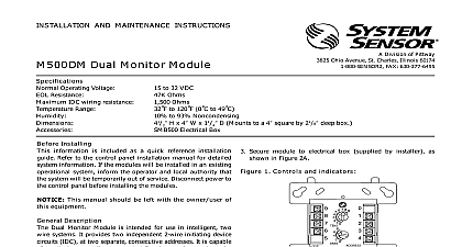
INSTALLATION AND MAINTENANCE INSTRUCTIONS Two wire Conventional Interface Module SENSOR Division of Pittway 3825 Ohio Avenue St Charles Illinois 60174 FAX 630 377 6495 Features to 120 F 0 to 49 C to 93 Noncondensing lbs 232 g H 4 W 11 4 D Mounts to 4 square by 21 8 deep electrical boxes activated reed switch Mount Box for 500 series modules Magnet for testing devices Line Terminals 1 2 32 VDC Max 24 VDC no communication mA Max Style D enabled mA Max 24V LED latched on Max Impedance Power Supply Requirements Terminals 3 4 must be interrupted to reset detectors The interface module must have a minimum of 15 VDC at terminals 3 and 4 function properly Ground fault detection must be accomplished by the control panel Device Circuit IDC Terminals 6 7 8 9 Loop Impedance 28.2 VDC filtered regulated and power limited RMS Max mA per module to 30.3 VDC Ripple 100mV RMS Max mA Max Max Current Current in Standby Current Resistance loop current is sufficient to ensure operation of one alarmed detector per zone mA Max maximum IDC voltage to 2.4 mA mA minimum B class B Style D class A ohm nominal Installing information is included as a quick reference installa guide Refer to the appropriate installation manual for system information If the modules will be in in an existing operational system inform the opera and local authority that the system will be temporarily of service Disconnect power to the control panel before the modules This manual should be left with the owner user this equipment Description M502M Interface Module allows intelligent panels to and monitor two wire conventional smoke detec Manuals Online All two wire detectors being monitored must be UL with the module module is addressed through the communication line intelligent systems When the module is interrogated it the status of one zone of two wire detectors to an control panel Status conditions are reported as open or alarm The interface module supervises zone of detectors and the connection of an external supply rotary decade switches allow setting module addresses 00 A status LED indicator is provided and is con by code command from the control panel The mod provides a magnetically activated test switch for testing module electronics and connections to the control see Figure 1 Requirements insure proper operation this module shall be connected compatible intelligent control panels only Conventional smoke detectors must be UL compatible with the module A list of compatible two wire convention detectors is below M502M Interface Module can be tested with a test available from System Sensor M02 04 01 see Fig 1 The magnet test checks the module electronics connections to the control panel Interfaced two wire must be tested independently Test two wire de per manufacturer installation instructions 1 Module controls and indicators t LED 5 5 DECADE SWITCHES TEST 2A Mounting module with barrier 2B Contents interface module includes the following items ohm end of line resistor A2143 10 Two wire interface module Off white cover plate pack for cover plate M502M Interface Module mounts directly to 4 inch electrical boxes as shown in Figure 2 The box must a minimum depth of 2 1 8 inches All wiring must conform to applicable local codes and regulations When using control in nonpower limited applications the Sys Sensor CB500 Module Barrier must be used to UL requirements for the separation of power and nonpower limited terminals and wir The barrier must be inserted in a 4 x4 x21 8 box and the control module must be into the barrier and attached to the junction Figure 2A The power limited wiring must be into the isolated quadrant of the module Figure 2B Install module wiring in accordance with the job draw and appropriate wiring diagrams Figures 3 5 Set the address on the module per job drawings Secure module to electrical box supplied by installer shown in Figure 2A Two wire System Sensor Smoke Detectors for Use with M502M with Zone Identifier A with Thermal with Thermal with Thermal Manuals Online Interface Module Wiring Diagrams 3 Interface two wire conventional detectors NFPA Style B MODULES TO LISTED CONTROL ONLY PANEL OR DEVICE LINE VDC MAX PAIR RECOMMENDED NEXT 9 8 7 6 WIRING MUST BE POWER LIMITED CONVENTIONAL DETECTOR DEVICE CIRCUIT IDC NFPA STYLE B LIMITED 92ma MAX 30.3 VDC MAX INSTALLATION WIRING MUST NOT EXCEED OHMS 12 18 AWG NOT MIX FIRE ALARM INITIATING SUPERVISORY SECURITY DEVICES ON THE SAME MODULE BRANCH CIRCUIT NEXT INTERFACE MODULE SUPERVISES SUPPLY AND DETECTOR LOOP NOT LOOP WIRE UNDER TERMINALS BREAK WIRE TO PROVIDE SUPERVISION OF CONNECTIONS MUST BE UL LISTED COMPATIBLE WITH MODULE DETECTORS PER MANUFACTURER INSTRUCTIONS EOL BATTERY BACKUP SWITCHED POWER SUPPLY REQUIREMENTS ON PAGE 3 TO THE INTERFACE MODULE BE EXTERNALLY SWITCHED TO THE DETECTORS A TC810A MODULE CAN BE USED TO POWER FROM A STANDARD SUPPLY SEE FIGURE 5 4 Interface two wire conventional detectors NFPA Style D LINE VDC MAX PAIR RECOMMENDED MODULES TO LISTED CONTROL ONLY PANEL OR DEVICE WIRING MUST BE POWER LIMITED CONVENTIONAL DETECTOR DEVICE CIRCUIT IDC NFPA STYLE D LIMITED 92ma MAX 30.3 VDC MAX INSTALLATION WIRING MUST NOT EXCEED OHMS 12 18 AWG NOT MIX FIRE ALARM INITIATING SUPERVISORY SECURITY DEVICES ON THE SAME MODULE NEXT 9 8 7 6 EOL RESISTOR AT TERMINALS 9 INCLUDED BATTERY BACKUP SWITCHED POWER SUPPLY REQUIREMENTS ON PAGE 3 TO THE INTERFACE MODULE BE EXTERNALLY SWITCHED TO THE DETECTORS A TC810A MODULE CAN BE USED TO POWER FROM A STANDARD SUPPLY SEE FIGURE 5 BRANCH CIRCUIT NEXT INTERFACE MODULE SUPERVISES SUPPLY AND DETECTOR LOOP NOT LOOP WIRE UNDER TERMINALS BREAK WIRE TO PROVIDE SUPERVISION OF CONNECTIONS MUST BE UL LISTED COMPATIBLE WITH MODULE DETECTORS PER MANUFACTURER INSTRUCTIONS Manuals Online 5 M500C series control module switching a power supply controls switched 24 VDC external power M502M MODULES TO LISTED CONTROL ONLY PANEL OR DEVICE