System Sensor M502M Manual

File Preview
Click below to download for free
Click below to download for free
File Data
| Name | system-sensor-m502m-manual-0386215974.pdf |
|---|---|
| Type | |
| Size | 1.50 MB |
| Downloads |
Text Preview
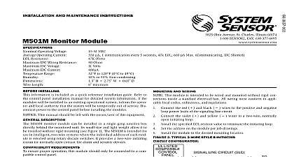
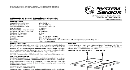
INSTALLATION AND MAINTENANCE INSTRUCTIONS 3825 Ohio Avenue St Charles Illinois 60174 FAX 630 377 6495 DC Voltage Voltage VDC power limited Volts RMS maximum per module to 120 0 to 49 to 93 Non condensing H x 4 W x 11 D Mounts to a 4 square by 21 deep box Electrical Box Interface Module to 32 VDC Operating Voltage LED on Current Draw 1 communication and 1 LED flash every 5 seconds 3.9k eol Operating Current Ohms Resistance Ohms IDC wiring resistance Supply Voltage between Terminals T10 and T11 Range Installing information is included as a quick reference installation Refer to the control panel installation manual for detailed information If the modules will be installed in an existing system inform the operator and local authority that system will be temporarily out of service Disconnect power to control panel before installing the modules This manual should be left with the owner user of equipment Description M502M Interface Module is intended for use in intelligent systems where the individual address of each module selected using the built in rotary decade switches This module intelligent panels to interface and monitor two wire con smoke detectors It transmits the status normal open alarm of one full zone of conventional detectors back to the panel All two wire detectors being monitored must be UL with this module The M502M has a panel controlled indicator Requirements ensure proper operation these modules shall be connected to compatible system control panels only M502M mounts directly to 4 square electrical boxes see Fig 2A The box must have a minimum depth of 21 Surface electrical boxes SMB500 are available from System Sen 2A Module mounting barrier appropriate wiring diagrams in Figure 2A 2B All wiring must conform to applicable local codes ordi and regulations This module is intended for power lim wiring only Install module wiring in accordance with the job drawings Set the address on the module per job drawings Secure module to electrical box supplied by installer as 1 Controls and indicators with Thermal Two wire System Sensor Smoke Detectors for Use with M502M with Zone Identifier A in combination with MTL isolator model MTL3043 with Thermal with Thermal ANY FAULT IN THE POWER SUPPLY IS LIMITED TO THAT ZONE AND DOES NOT RESULT IN A FAULT IN A SEPARATE ZONE 3 Interface two wire conventional detectors NFPA Style B BRANCH CIRCUIT NEXT INTERFACE MODULE SUPERVISES SUPPLY AND DETECTOR LOOP NEXT TO THE INTERFACE MODULE BE EXTERNALLY SWITCED TO THE DETECTORS AN M500R RELAY MODULE CAN BE USED TO POWER FROM A STANDARD SUPPLY SEE FIGURE 5 BATTERY BACKUP SWITCHED DC POWER SUPPLY EOL NOT LOOP WIRE UNDER TERMINALS BREAK ALL WIRE TO PROVIDE SUPERVISION OF CONNECTIONS MUST BE UL LISTED COMPATIBLE WITH INSTALL DETECTORS PER MANUFACTURER INSTRUCTIONS PANEL OR DEVICE LINE CIRCUIT SLC VDC MAX PAIR RECOMMENDED MODULES TO LISTED CONTROL PANELS ONLY WIRING MUST BE POWER LIMITED NOT MIX FIRE ALARM INITIATING SUPERVISORY SECURITY DEVICES ON THE SAME MODULE 4 Interface two wire conventional detectors NFPA Style D TO THE INTERFACE MODULE BE EXTERNALLY SWITCED TO THE DETECTORS AN M500R RELAY MODULE CAN BE USED TO POWER FROM A STANDARD SUPPLY SEE FIGURE 5 BRANCH CIRCUIT NEXT INTERFACE MODULE SUPERVISES SUPPLY AND DETECTOR LOOP NEXT PANEL OR DEVICE LINE CIRCUIT SLC VDC MAX PAIR RECOMMENDED MODULES TO LISTED CONTROL PANELS ONLY WIRING MUST BE POWER LIMITED NOT MIX FIRE ALARM INITIATING SUPERVISORY SECURITY DEVICES ON THE SAME MODULE BATTERY BACKUP REGUALTED POWER SUPPLY EOL RESISTOR AT TERMINALS 9 INCLUDED A2143 10 NOT LOOP WIRE UNDER TERMINALS BREAK ALL WIRE TO PROVIDE SUPERVISION OF CONNECTIONS MUST BE UL LISTED COMPATIBLE WITH INSTALL DETECTORS PER MANUFACTURER INSTRUCTIONS 5 Relay control module used to disconnect a power supply ANY FAULT IN THE POWER SUPPLY IS LIMITED TO THAT ZONE AND DOES NOT RESULT IN A FAULT IN A SEPARATE ZONE NEXT LIMITED DC SUPPLY FOR FIRE WITH BACKUP CONTROL PANEL OR DEVICE LINE CIRCUIT SLC VDC MAX PAIR RECOMMENDED MODULES TO LISTED CONTROL PANELS ONLY ANY FAULT IN THE POWER SUPPLY IS LIMITED TO THAT AND DOES NOT RESULT IN A FAULT IN A SEPARATE ZONE Limited Warranty Sensor warrants its enclosed product to be free from defects in materi and workmanship under normal use and service for a period of three years date of manufacture System Sensor makes no other express warranty the enclosed product No agent representative dealer or employee of Company has the authority to increase or alter the obligations or limita of this Warranty The Company obligation of this Warranty shall be to the replacement of any part of the product which is found to be in materials or workmanship under normal use and service during three year period commencing with the date of manufacture After phon System Sensor toll free number 800 SENSOR2 736 7672 for a Return number send defective units postage prepaid to Honeywell Rojas Drive Suite 700 El Paso TX 79936 USA Please include a note the malfunction and suspected cause of failure The Company shall be obligated to replace units which are found to be defective because of unreasonable use modifications or alterations occurring after the of manufacture In no case shall the Company be liable for any con or incidental damages for breach of this or any other Warranty or implied whatsoever even if the loss or damage is caused by Company negligence or fault Some states do not allow the exclusion limitation of incidental or consequential damages so the above limitation exclusion may not apply to you This Warranty gives you specific legal and you may also have other rights which vary from state to state System Sensor 03 11