System Sensor MOD400R Manual

File Preview
Click below to download for free
Click below to download for free
File Data
| Name | system-sensor-mod400r-manual-5931472086.pdf |
|---|---|
| Type | |
| Size | 605.29 KB |
| Downloads |
Text Preview
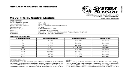
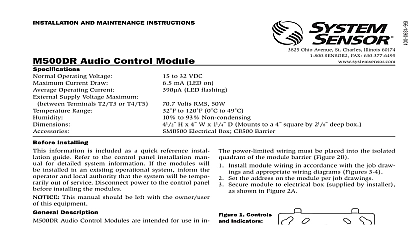
INSTALLATION AND MAINTENANCE INSTRUCTIONS Test Module Description MOD400R Test Module is a tool testing the relative of 100 200 300 400 and 500 Series smoke only It CANNOT be used on 800 Series detectors consists of a test module and interface cord for connect the module to the detector being tested battery powered module is equipped with two color banana jacks for the connection of any analog or dig DC voltmeter having a sensitivity of 10 k or greater an added convenience two adhesive backed Velcro are also supplied for attaching the module to the being used during testing module function is under the control of a 3 position a 2 position slide switch on the side of the unit combinations of positions of these two switches the module to test conventional and analog ioniza and photoelectronic smoke detectors as well as check the battery In addition the 3 position switch SW1 has center OFF position for turning off the module Therefore battery life by always setting this switch to OFF the module is not in use Setup Connect a voltmeter having a sensitivty of 10 k or to the banana jacks on the side of the Be sure to connect the positive test lead to red jack and the negative lead to the black Connect the interface cord to the RJ 11 telephone jack on bottom edge of the module Test the MOD400R battery as described in BATTERY Detector Testing Ion Prepare the MOD400R for testing by performing the pro Ohio Avenue St Charles Illinois 60174 FAX 630 377 6495 1 to insert and retract this plug in the direction shown result in damage to the pins Handle with care Inspect regularly for damage to ensure proper operation detector This corresponds to the NOMINAL SENS on the label the voltmeter displays a voltage outside the RANGE it indicates that the detector cleaning or repair Disconnect the MOD400R from the detector and set SW1 OFF Photoelectronic Detectors Prepare the MOD400R for testing by performing the pro in MOD400R SETUP in MOD400R SETUP Set the voltmeter to measure at least 3 VDC Make sure that power is applied to the detector to be Set the voltmeter to measure at least 3 VDC Make sure that power is applied to the detector to be Set SW1 to its A position and the 2 position switch SW2 Set SW1 to its B position and the 2 position switch SW2 CONV CONV See Figure 1 Insert the test plug into the test module See Figure 1 Insert the test plug into the test module on the detector voltmeter should display a voltage that falls in the RANGE printed on the label on the back of on the detector voltmeter should display a voltage that falls in the RANGE printed on the label on the back of detector This corresponds to the NOMINAL SENS on the label the voltmeter displays a voltage outside the RANGE it indicates that the detector cleaning or repair Testing MOD400R operates from a single 9 volt alkaline bat whose life expectancy is approximately one year it should be tested before each use of the to ensure accurate sensitivity measurements test the battery Make sure that the MOD400R is NOT connected to any Set a voltmeter having a sensitivity of at least 10 k or sensor measure 9 VDC Connect the meter to the banana jacks on the side of the Be sure to connect the positive lead to the jack and the negative lead to the black Set SW1 to its A position and read the meter It should at least 5.5 VDC If it does not replace the 9 volt battery Disconnect the MOD400R from the detector and set SW1 OFF Sensors The MOD400R can be used to test the sensitivity of those sensors connected to control panels that NOT use drift compensation Prepare the MOD400R for testing by performing the pro in MOD400R SETUP Set the voltmeter to measure at least 3 VDC Make sure that power is applied to the sensor to be test INT Set SW1 to its B position and the 2 position switch SW2 See Figure 1 Insert the test plug into the test module on the detector voltmeter should display a voltage that falls in the RANGE printed on the label on the back of sensor This corresponds to the NOMINAL SENS on the label the voltmeter displays a voltage outside the RANGE it indicates that the sensor cleaning or repair Disconnect the MOD400R from the detector and set SW1 OFF Limitations of the MOD400R MOD400R is designed to assure that each smoke detector is within listed and marked sensitivity range per NFPA 72 The MOD400R however initiate a detector sensor alarm Therefore the meets only part of NFPA 72 testing standards fluctuations in readings may be experienced on any device at any time and do not indicate a defect or sensitivity shift provided the is within the specified range These fluctuations are to be expected MOD400R and its associated smoke detectors sensors contain elec parts and though they are designed to last over 10 years any of these can fail at any time Therefore it is recommended to test your detectors sensors per NFPA 72 at least semiannually Regular clean and testing of your fire detection system will measurably reduce your liability risks and minimize nuisance alarms Limited Warranty Sensor warrants its enclosed MOD400R to be free from defects in and workmanship under normal use and service for a period of years from date of manufacture System Sensor makes no other warranty for this MOD400R No agent representative dealer or of the Company has the authority to increase or alter the obli or limitations of this Warranty The Company obligation of this shall be limited to the repair or replacement of any part of the which is found to be defective in materials or workmanship normal use and service during the three year period commencing the date of manufacture After phoning System Sensor toll free 800 SENSOR2 736 7672 for a Return Authorization number defective units postage prepaid to System Sensor Repair RA 3825 Ohio Avenue St Charles IL 60174 include a note describing the malfunction and suspected cause of The Company shall not be obligated to repair or replace units are found to be defective because of damage unreasonable use or alterations occurring after the date of manufacture In no shall the Company be liable for any consequential or incidental dam for breach of this or any other Warranty expressed or implied what even if the loss or damage is caused by the Company negligence fault Some states do not allow the exclusion or limitation of incidental consequential damages so the above limitation or exclusion may not to you This Warranty gives you specific legal rights and you may have other rights which vary from state to state System Sensor 1996