System Sensor OSI-R-SS Quick Start Guide

File Preview
Click below to download for free
Click below to download for free
File Data
| Name | system-sensor-osi-r-ss-quick-start-guide-5723496081.pdf |
|---|---|
| Type | |
| Size | 1.77 MB |
| Downloads |
Text Preview
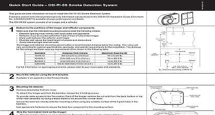
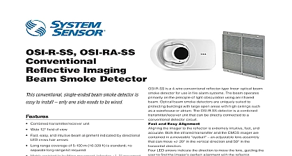
1 Start Guide OSI R SS and OSI RA SS Smoke Detection System guide provides information on how to install the OSI R SS and OSI RA SS Smoke Detection System product and critical product security information can be found in the OSI R SS and OSI RA SS Installation Document No E56 6572 33777 available at www systemsensor com beam OSI R SS and OSI RA SS system consists of an Imager and a reflector the positions of the Imager and reflector components sure that the intended mounting locations meet the following criteria Detector spacing must comply with local codes and standards Reflector must be located within the Field of View FOV of the Imager Clear path between the reflector and Imager Mounted well above the head height of people and obstructions Avoid direct sunlight onto the units Imager and reflector should be placed within a recommended distance below the ceiling This value will according to regional specifications geometry and specific requirements for the installation The distance flat ceilings and basic spacing requirements S is shown in the following table m 60 ft m 45.9 ft m 49.2 ft m 45.9 ft full information on spacing requirements please refer to your local codes and standards to 1000 mm 11.8 to 39.4 in from Ceiling H mm 12 in minimum to 600 mm 1 to 23.6 in to 600 mm 1 to 23.6 in 72 Spacing S the reflector using the drill template in an appendix in the Product Guide the detector detachable front rim cover detach the Imager part from the backbox loosen the 3 holding screws provide cable access to the Termination Card of the Imager remove the cut outs from the back bottom or top the main assembly by using a sharp blade to cut around the circular discs the back box directly onto the mounting surface using any suitable number of the 5 pilot holes in the appropriate fasteners to secure the back box component to the mounting surface the Termination Card on the Imager Wire the initiating device circuit on the Imager Termination Card using the FIRE and FAULT relay terminals for four wire device connection For all relay connections break wire run to allow monitoring Wire external power to the unit via the POWER terminals Wire the Remote Indicator and or remote test or reset units if required Securely connect the wires to the plug in terminals and engage in the receptacles at the back of the Imager Switch on the heater if the installation requires so Re attach the Imager to the back box Remove the protective film from the lens surface of the imager TBD Connect power to the Imager Analog addressable Input zone modules can also be used with the system For further detail please the relevant FACP Product Guide S minimum 9.1m maximum First 3.0m S maximum S ft 5m minimum ft 100m maximum Distances according to NFPA 72 for the fixing the detector holes knock outs knock out 4 J Box knock outs NO COM COM NC NO Common Common NC Test Reset Input Trouble Output Alarm Output In In In In on off switch heater ON IN POWER OUT IN POWER OUT IN OUT IN OUT COM COM COM COM NO NO NO NO ALARM OUTPUT TROUBLE OUTPUT TEST INPUT ALARM OUTPUT TROUBLE OUTPUT TEST INPUT A If other sensors are installed on the same loop a listed end of line power supervision module is required Terminals Alarm Output Trouble Output Test Reset Input ohm LED connections Laser Tool down Initialization and commissioning that neither you nor any other objects are in the line of sight between the detector and the reflector and to manually align the Imager to the reflector The OSP 002 Laser Alignment Tool can be used for the rough if the system is to be installed at longer distances or in heavy lit environments these steps to adjust the optical sphere of the detector component to align the system Make sure the lever is the 3 o position The 4 arrows will intuitively guide the user to optimal eyeball alignment the alignment process will start with all arrows red Gently move the eyeball until all arrows and the middle green LED blink green for the eyeball to be optimal When all arrows are green gently lock the eyeball by moving the lever down till the eyeball is solidly locked lever is now in the 5 o position and you feel the resistance of the locked position locking the eyeball an internal switch is activated and the detector will now start its initiation or commissioning A normal commissioning process takes roughly 10 seconds During the commissioning process the path must remain clear from object intrusions In this process cycle the detector will measure size of the in the FOV and set the sensitivity automatically to the optimum sensitivity for the specific distance going in operational mode the detector will show its set sensitivity This is shown by blinking the 4 arrows the colour yellow reflecting the of selected obscuration sensitivity The key is 1 blink 25 2 blinks 30 blinks 40 and 4 blinks 50 After 5 seconds the scenario will be repeated a second time and the arrows go out and the front OK LED blinks green The detector is now in operation and working correctly paintable rim can now be snapped over the front to secure the locking lever and to hide the alignment LEDS locking mechanism the cover also secures the locking lever in position Testing the installation the commissioning the detector must be tested for correct alarming by using the OSP 004 test filter at the or using the remote test station When using the RTS151KEY for testing the detector the remote fault will blink the set sensitivity of the detector The number of blinks similar to section 5 will represent the set and the sequence is repeated every 3 seconds till the detector is reset reset fault relay is non latching but the alarm relay is latching The Imager alarm can be reset by shortly dropping supply voltage or by using a reset station after a Power Failure a power failure of any duration when the supply is restored the detector will check the possible new situation it memorized data the reflector is found in the same position and all parameters are within acceptable limits the detector will its operation and go out of fault condition any significant parameters have changed it will remain in a fault condition and a re initialization will be required Modes and Troubleshooting Guide OSI R SS and OSI RA SS and Remote Output means Tips and Alarm on Quick Blinks Quick Blinks Quick Blinks the set by of blinks 1 Repeats every 3 till reset Power from state in 3 00 position commissioning is lever in 6 00 to start completion initialization or reset Test Filter RTS151KEY Test Term Drift Out of 20 blockage detector out of saturated All wiring correctly done Address switches set Ready to perform Follow guidance from the arrows to correctly align Commissioning and sensitivity Do not interrupt beam Detector oper