System Sensor OSY2 Manual

File Preview
Click below to download for free
Click below to download for free
File Data
| Name | system-sensor-osy2-manual-4085169723.pdf |
|---|---|
| Type | |
| Size | 725.79 KB |
| Downloads |
Text Preview
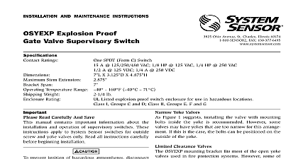
INSTALLATION AND MAINTENANCE INSTRUCTIONS 3825 Ohio Avenue St Charles Illinois 60174 FAX 630 377 6495 Gate Valve Switch Ratings 10 A 125 250 VAC 2.5 A 24 VDC 53 X 31 X 31 Stem Extension 25 Stem Extension 5 Span 63 Temperature Range 32 120 0 49 Weight 23 lb Rating NEMA Type 3R when mounted with the actuator vertical cover on top as tested by Laboratories Inc IP54 Patent Number 5,213,205 Read Carefully And Save instruction manual contains important information the installation and operation of supervisory switches who install supervisory switches for use by oth must leave this manual or a copy of it with the user instructions apply to System Sensor switches for screw and yoke valves only Read all instructions before beginning installation NOT use this switch in explosive or potentially explo atmospheres NOT leave unused wires exposed supervisory switch installations must comply with local and ordinances and the requirements of the author having jurisdiction Additional information is available National Fire Protection Association standards NFPA 13 13R 71 and 72 Installation Considerations OSY2 Supervisory Switch can be mounted on open valves between 1 and 12 in diameter in the posi shown in Figure 1 only If the switch is installed with actuator pointing upward water may leak into the of the switch Therefore do NOT install the OSY2 its actuating lever pointing upward OSY2 models are equipped with a ground screw inside switch housing near the conduit exit hole for those where grounding is required ACCEPTABLE 1 Yoke Valves Figure 2 suggests installing the valve with mounting inside the yoke is recommended However some may have yokes that are too narrow for this arrange If this is the case the bolts can be positioned on the of the yoke Clearance Valves OSY2 mounting bracket fits most of the open yoke used in fire protection systems However some of valves especially those less than 11 in diameter irregularly shaped yokes or such limited clearances the clamping bar cannot be installed properly and or causes the valve to bind If this is the case the use of J is required to attach the OSY2 to the valve see J Bolt Figure 2 J bolts can be purchased separately by the OSYRK Replacement Kit Instructions Figures 2 and 3 as required while performing the pro that follows step 1 on valves 11 in diameter and smaller Proceed directly to step 2 if the switch is being on a valve larger than 11 in diameter 1 I56 0393 008R 2 Detail 2 I56 0393 008R 3 STEM THREADED VALVE HEX BAR NOT SHOWN HEX NUT BOLT Remove and discard the two C clips and roller from the lever Set the valve to its fully open position Remove the OSY2 Switch from the carton and adjust the posi of the retaining washers to provide sufficient bolt for the yoke thickness of the valve Position the switch on the valve with the bolts on the preferably or outside of the yoke depending on Adjust the position of the OSY2 as far as pos from the valve gland and in a location where the lever contacts the unthreaded section of the stem if the valve stem is already grooved proceed to step 6 When the switch is in position on the valve slide the end of the clamping bar onto the bolts and under retaining washers If necessary adjust the length of actuating lever by loosening the screw on the cam the lever in or out as appropriate and retight the screw The lever is properly adjusted when it the clamping bar Tighten the nuts by hand and the OSY2 until the second switch trip points are as the lever rests on the valve stem This approxi the final position of the OSY2 after the valve stem grooved Carefully check all clearances of the bolts mounting bracket clamping bar and OSY2 Adjust the position as necessary If clearance is a refer to the Limited Clearance Valves page 1 of this manual Mark the point on the valve stem where the actuating contacts the valve stem Remove the OSY2 by loosening the nuts and sliding the bar from beneath the washers Remove the from the valve and set it aside a Valves 11 in diameter and smaller only Use a 1 untapered round file to file a groove 3 in the valve stem at the mark that was made step 4 Be sure to remove any burrs resulting from filing to avoid damaging the valve stem packing b Valves larger than 11 inches in diameter only Use untapered round file to file a groove 1 deep in 3 valve stem at the mark that was made in step 4 sure to remove any burrs resulting from the filing avoid damaging the valve stem packing gland Mount the switch loosely with the actuating lever cen in the groove When the switch is in position on valve slide the open end of the clamping bar onto bolts and under the washers as indicated in Figure Ensure that the actuating lever does not hit the inside the cover or the clamping bar at any point in its If it does adjust the length of the lever by loos the screw sliding the lever in or out as needed retightening the screw Adjust the supervisory switch position on the valve that both switches are depressed COM to B circuit when the actuating lever is in the groove with valve in the full open position The COM to B cir should close when the valve is closed 1 of its or 2 full turns of the handle whichever is less switch produces an audible