System Sensor PS24LO and PS24LOW Manual

File Preview
Click below to download for free
Click below to download for free
File Data
| Name | system-sensor-ps24lo-and-ps24low-manual-4086173295.pdf |
|---|---|
| Type | |
| Size | 693.27 KB |
| Downloads |
Text Preview
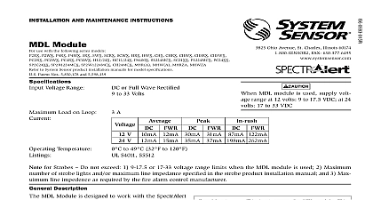
INSTALLATION AND MAINTENANCE INSTRUCTIONS and PS24LOW Strobes Strobe This strobe is listed to the 16 to 33 VDC UL limits 1 100 Information National Fire Protection Association has published codes and recommended practices for the installation and of the above appliances Therefore the installer must be PS24 model PS24 optional strobe can be added to the SSK451 Notes tested after installation in accordance with the duct detector 2 with PA400 Sounder optional strobes are interconnected to the PA400 by first combined sounder and adapter plate to the electrical outlet the slot closest to the field wiring terminals Grasp the catch with SSK451 Multi signaling Accessory TERMINAL TOP 3 SMOKE Strobe Lens refer to insert for the Limitations of Fire Alarm Systems Limitations of Sounders and Strobes strobe is for supplementary signaling use only sounder or sounder strobe combination will not work without The sounder or sounder strobe gets its power from the fire or panel monitoring the alarm system If power is cut off for any signal strobe may not be seen an area where it can be seen by building occupants The strobe not be installed in direct sunlight or areas of high light intensity strobe may be seen by the visually impaired signal strobe may cause seizures Individuals who have a posi photic response to visual stimuli with seizures such as epileptics Limited Warranty Sensor warrants its enclosed sounder strobe to be free from obligations or limitations of this Warranty The Company obliga free number 800 SENSOR2 736 7672 for a Return Authorization send defective units postage prepaid to System Sensor Repair include a note describing the malfunction and suspected cause are found to be defective because of damage unreasonable use or alterations occurring after the date of manufacture In