System Sensor retroplate strobes

File Preview
Click below to download for free
Click below to download for free
File Data
| Name | system-sensor-retroplate-strobes-6048759231.pdf |
|---|---|
| Type | |
| Size | 1.77 MB |
| Downloads |
Text Preview
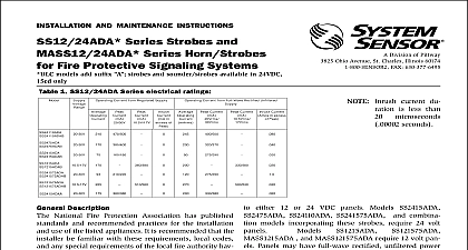
INSTALLATION AND MAINTENANCE INSTRUCTIONS Series Strobes and Series Horn Strobes Fire Protective Signaling Systems models add suffix strobes and sounder strobes available in 24VDC only Table 1 SS12 24ADA Series electrical ratings Current from Regulated Supply Current from Full Wave Rectified Unfiltered of in Current Current Current in excess Peak SENSOR Division of Pittway 3825 Ohio Avenue St Charles Illinois 60174 FAX 630 377 6495 current du is less than microseconds seconds Description National Fire Protection Association has published and recommended practices for the installation use of the listed appliances It is recommended that the be familiar with these requirements local codes any special requirements of the local fire authority hav jurisdiction Multi Alert sounder and signaling strobe are intended be connected to the alarm indicating circuit of a UL fire alarm control panel Both are compatible with DC supervision The electronic sounder can be connected either 12 or 24 VDC panels Models SS2415ADA SS24110ADA SS241575ADA and combina models incorporating these strobes require 24 volt and MASS121575ADA require 12 volt pan Panels may have full wave rectified unfiltered power The strobes produce one flash per second nomi with continuous nominal voltage applied Models MA12 24D is suitable for outdoor applications 35 cid 176 to C when it is used with a WBB Weatherproof Back Box signaling strobe is rated for 0 cid 176 to 49 cid 176 C and is NOT 2 Sound Output and Current Ratings for the MA12 24D Hz on Tabs Note 1 Whoop Continuous Alternating Interrupted Continuous Interrupted Frequency Warble ma Regulated Unfiltered 38 56 28 45 34 46 35 56 38 59 23 33 34 47 30 47 dBA 3 dBA 4 Figure 2 for tab clip removal storage 1 2 All models can be powered using full wave rectified unfiltered Under no SS24ADA or series devices input voltage exceed 33 VDC or be than 16 VDC 16 33Vrms for full wave rectified unfiltered Under no circumstances can the MA12 24D input exceed 33 VDC or be less than 9.6 VDC Under no cir can a SS12ADA or MASS12ADA series device input exceed 18.7 VDC or be less than 9.6 VDC 9.6 for full wave rectified unfiltered supplies 3 Measured at 10 feet in an anechoic chamber 4 Measured in a UL reverberant room Manuals Online for outdoor use rated light output of the SS2415ADA SS1215ADA MASS1215ADA and MASS121575ADA 15 cd See Figure 1 is 75 cd See Figure 1 output of SS2475ADA and the device terminal connection in order to main electrical supervision Strobe and strobe combination are designed for wall mount ONLY sounder is 1 1 4 deep Back boxes must be 4 by at least 1 1 2 deep 2 1 8 deep is strobes must be mounted so that the top of the lens is inches 61 cm below ceilings or as required by the having jurisdiction rated is 110 cd See Figure 1 output of SS24110ADA and The light output at 0 cid 176 viewing angle for SS12 and MASS12 241575ADA models is 75 See Figure 1 Sounder mounting Surface Mount See Fig 7 Semi Flush Mount See Fig 10 and 13 Flush Mount See Fig 12 Sounder Strobe combination mounting one of eight sounds can be selected on the electronic as indicated in Table 2 The sound selected deter the maximum current and sound power output per See Table 1 for these values Sounder Strobe Operation may be applications where it is desirable to drive the and strobe as independent devices The System MASS12 24ADA series sounder strobes are easily for this capability The terminal connection for application is shown in Figure 6 Independent strobe in a coded system requires a separate uncoded supply for the strobe General head screws are used to attach each device or of devices to the electrical outlet box head screws are used to attach accessories to the Refer to Figures 3,4,5 and 6 for wiring methods Do not loop wires under the terminal screw Wires the device to the panel must be broken Surface Mount See Fig 9 Semi Flush Mount See Fig 10 and 13 mounting requires the use of the deep box Part or equivalent Determine which of the two device will be used to attach the device to the box Mount flush plate to the sounder using the other two holes two 1 inch phillips head screws and two square Strobe mounting Surface Mount See Fig 8 Semi Flush Mount See Fig 11 procedures must conform to all applicable and the requirements of the authority having The rated output of the sounder is specified at 10 It cannot be assumed that the output will the NFPA standard of 15 dB over ambient at all locations within a room Additional may be needed to ensure sound output complies with NFPA requirements Limitations of Sounder Strobes Sounder and or Strobe will not work without power The sounder gets its power from the fire security panel monitoring the alarm If power is cut off for any reason the sounder strobe will not pro the desired audio or visual warning Sounder may not be heard The loudness of the sounder meets or current Underwriters Laboratories standards However the may not alert a sound sleeper or one who has recently used drugs has been drinking alcoholic beverages The Sounder may not be heard it is placed on a different floor from the person in hazard or if placed too away to be heard over the ambient noise such as traffic air condition machinery or music appliances that may prevent alert persons from the alarm The Sounder may not be heard by persons who are impaired Signal Strobe may not be seen The electronic visual warning signal flashes at least once every three seconds meets or exceeds current Un Laboratories standard 1971 and uses an extremely reliable xe Manuals Online flash tube The visual warning signal is suitable for direct viewing and be installed within an area where it can be seen by building occu The strobe must not be installed in direct sunlight or areas of high intensity over 60 foot candles where the visual flash might be disre or not seen The strobe may not be seen by the visually im signal strobe may cause seizures Individuals who have a positive response to visual stimuli with seizures such as epileptics should prolonged exposure to environments in which strobe signals in this strobe are activated Sensor recommends that the Multi Alert Sounder and Signal always be used in combination so that the risks from any of the limitations are minimized signal strobe cannot operate from coded power supplies Coded supplies produce interrupted power The strobe must have an unin source of dc power in order to operate correctly