System Sensor RR2 Manual
File Preview
Click below to download for free
Click below to download for free
File Data
| Name | system-sensor-rr2-manual-8619347520.pdf |
|---|---|
| Type | |
| Size | 692.79 KB |
| Downloads |
Text Preview
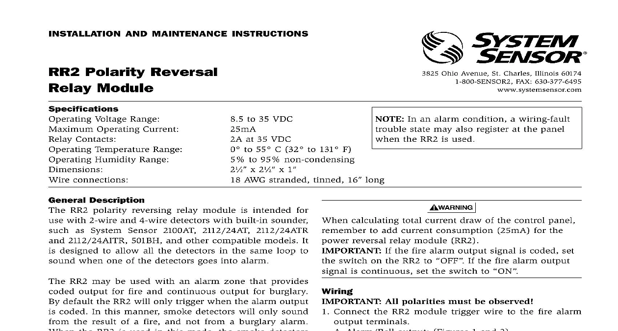
INSTALLATION AND MAINTENANCE INSTRUCTIONS Polarity Reversal Module Voltage Range 8.5 to 35 VDC Operating Current 25mA Contacts 2A at 35 VDC Temperature Range 0 to 55 C 32 to 131 F Humidity Range 5 to 95 non condensing 21 x 21 x 1 connections 18 AWG stranded tinned 16 long Ohio Avenue St Charles Illinois 60174 FAX 630 377 6495 In an alarm condition a wiring fault state may also register at the panel the RR2 is used Description RR2 polarity reversing relay module is intended for with 2 wire and 4 wire detectors with built in sounder as System Sensor 2100AT 2112 24AT 2112 24ATR 2112 24AITR 501BH and other compatible models It designed to allow all the detectors in the same loop to when one of the detectors goes into alarm RR2 may be used with an alarm zone that provides output for fire and continuous output for burglary default the RR2 will only trigger when the alarm output coded In this manner smoke detectors will only sound the result of a fire and not from a burglary alarm the RR2 is used in this mode the smoke detectors provide for coded alarm signals if required by the RR2 can also be set to only trigger on continuous zone signals When used in this mode it will not from a coded fire alarm signal This manual shall be left with the owner user of equipment If your panel configuration does not match any of provided wiring diagrams please contact System Sensor services at 1 800 SENSOR2 for assistance a mounting location in the control panel within of the provided wire leads Use a water isopropyl mixture 50 50 to clean the mounting surface surface to dry and remove paper backing from the and catch Stick the Velcro in the panel and the catch the back of the module then mount the module inside control panel Route terminals to the appropriate termi as noted below calculating total current draw of the control panel to add current consumption 25mA for the reversal relay module RR2 If the fire alarm output signal is coded set switch on the RR2 to If the fire alarm output is continuous set the switch to All polarities must be observed Connect the RR2 module trigger wire to the fire alarm terminals Alarm Bell output Figures 1 and 2 Connect the purple wire to the Alarm or Bell output Alarm relay normally open contact Figures 3 and 4 1 Connect one end of the alarm relay contact output positive auxiliary or detector power fire alarm 2 Connect the purple wire to the other end of the relay contact output Connect the red and black wires to the panel auxiliary detector power red to positive black to negative 2 wire models Connect the yellow and orange wires to the panel initiat circuit yellow to positive orange to negative 4 wire models Connect the yellow and orange wires to the panel detec power circuit yellow to positive orange to nega 2 wire models Connect the brown and white wires to the smoke detector circuit brown to positive white to negative 4 wire models Connect the brown and white wires to the smoke detec power circuit brown to positive white to negative 1 I56 1683 02 If your panel configuration does not match any of the following wiring diagrams please contact System Sensor services at 1 800 SENSOR2 for assistance Please refer to Figures 5 and 6 for Ademco Vista panels and Figure for DSC Power 832 panels 1 2 Wire system triggered from IAC bell circuit If optional Style A Class B wiring is used a second RR2 module must be added to enable concurrent loop reversal 2 4 Wire system triggered from IAC bell circuit LISTED signal alarm state POWER LISTED signal alarm state POWER LISTED Contact POWER Aux Aux 3 2 Wire system triggered from alarm relay contact If optional Style A Class B wiring is used a second RR2 module must be added to enable concurrent loop reversal 2 I56 1683 02 4 4 Wire system triggered from alarm relay contact Aux Aux LISTED Contact POWER RELAY energized Diagrams with Ademco Vista Panels connection diagrams enclosed show how to connect the 2100AT model smoke detector to the Vista panels using the Sensor power reversal relay module RR2 Please make sure that the smoke detectors are connected properly to zones specified in the wiring diagrams for proper operation of the smoke detectors 5 Connecting 2100AT smoke detectors to Ademco controls using RR2 module triggered from circuit SENSOR REVERSAL MODULE RR2 INSIDE CONTROL ENCLOSURE signal alarm state POWER WATT SENSOR SMOKE DETECTORS TO 16 DETECTORS ZONE SENSOR SMOKE DETECTORS TO 16 DETECTORS ZONE OHMS information The supervisory feature for the circuit must be turned off applicable control manual procedure Configuration switch on RR2 to 6 Connecting 2100AT smoke detectors to Ademco controls using RR2 module triggered from relay REQUIRED ON 5110XM 5100XM JUMPER W3 INTACT SENSOR REVERSAL MODULE RR2 INSIDE CONTROL ENCLOSURE WATT SENSOR SMOKE DETECTORS TO 16 DETECTORS ZONE SENSOR SMOKE DETECTORS TO 16 DETECTORS ZONE POWER FROM CONTROLS POWER OUTPUT ONLY OHMS information Program Auxiliary relay to on alarms Assign Auxiliary relay as an for zones programmed fire alarm response only 9 16 or 17 Configuration Set swit