System Sensor RRS-MOD

File Preview
Click below to download for free
Click below to download for free
File Data
| Name | system-sensor-rrs-mod-2854973061.pdf |
|---|---|
| Type | |
| Size | 762.21 KB |
| Downloads |
Text Preview
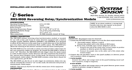
RRS MOD Relay Module RRS MOD reversing relay synchronization module the operation of 2 and 4 wire i3 Series equipped with a sounder compatible with 2 and 4 wire i3 detectors equipped with a all i3 sounders on a loop when one alarms all i3 sounders on the loop for a clear alarm signal usable with bell alarm alarm relay or NAC outputs a field selectable switch to accommodate both coded and alarm signals i3 detector silencing from the panel or keypad on 12 and 24 volt systems connections with quick connect harness and color coded ease The RRS MOD reversing relay synchronization includes a Velcro attachment for easy installation into the alarm control panel cabinet A quick connect harness and color wires simplify connections The RRS MOD module design is flexible to virtually any application It is compatible with both 2 4 wire i3 Series detectors operating over 12 V and 24 V systems module can be used with either bell alarm alarm relay or NAC and its field selectable switch accommodates both coded continuous alarm signals inspection To meet fire alarm requirements the RRS MOD relay synchronization module activates all i3 sounders on a when an individual sounder alarms Additionally it synchronizes output of the i3 sounders regardless of whether the panel alarm is continuous or coded to ensure a clear alarm signal Listings Specifications Specifications relay synchronization module shall be a System Sensor i3 The module shall allow all 2 wire and 4 wire i3 Series detectors equipped with a sounder on a loop to sound when one alarms The module shall a switch to toggle between coded mode and continuous mode When in coded mode the module shall synchronize the i3 sounders on the loop to the input signal When in continuous mode the module shall synchronize the i3 sounders on the loop to the ANSI S3.41 temporal coded pattern In either or continuous modes the RRS MOD module shall permit sounders to be silenced at the panel The RRS MOD module shall operate between 8.5 and 35 and shall provide 18 AWG stranded tinned conductors connected to a quick connect harness Specifications Temperature Range Connections Humidity Range Specifications Voltage in H 2.5 in W 1 in D 63 mm 63 mm 25 mm AWG stranded tinned 16 in length to 85 non condensing Operating Current Contact Rating 12 24 V 8.5 V 35 V mA A 35 VDC Diagrams These diagrams represent two common wiring methods Refer to the RRS MOD installation manual for additional wiring configurations LISTED signal alarm state POWER LISTED Contact IN OUT IN OUT RA RA IN OUT IN OUT RA RA POWER IN OUT IN OUT RA RA IN OUT IN OUT RA RA System Triggered from Alarm Bell Circuit System Triggered from Alarm Relay Contact Information No relay synchronization module for i3 Series smoke detectors System Sensor specifications subject to change without notice Visit systemsensor com for product information including the latest version of this data sheet


