System Sensor RTC Manual

File Preview
Click below to download for free
Click below to download for free
File Data
| Name | system-sensor-rtc-manual-1459603287.pdf |
|---|---|
| Type | |
| Size | 609.05 KB |
| Downloads |
Text Preview
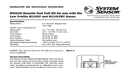
INSTALLATION AND MAINTENANCE INSTRUCTIONS Remote Test Coil Kit for use the B404B and B404BT Bases Requirements LED Coil Current Switch Switch Response Time Temperature Range x 2.75 W x 1.5 D lb 32 VDC 10 mA max 32 VDC 95 mA max mA max VA 32 VDC VA 32 VDC seconds max C to 60 14 F to 140 F RH noncondensing This manual should be left with the owner user this equipment 1 Description System Sensor Model RTC Remote Test Coil Kit allows the remote testing of duct detectors using the B404B or bases that are installed in inconvenient or difficult locations Model RTC can be installed in almost convenient location and can be attached to a standard X 4 electrical box National Fire Protection Association has published and practices for the installation and use of this As a result System Sensor recommends that the in be familiar with these standards and practices local and any special requirements of the authority hav jurisdiction Contents RTS451 Remote Test Station 8 x 1 4 pan head screws for mounting bracket Test Coil Replacement Ring Screw Pack 2 mounting Assembly screws Jumper with spade lugs M02 04 Test Magnet of the Model RTC consists of attaching the test to the mounting surface mounting the test coil on detector and routing the necessary wiring between This procedure assumes that the detector base is already installed and ready for Division of Pittway 3825 Ohio Avenue St Charles Illinois 60174 FAX 630 377 6495 Test Coil Mounting 2 Ring Replacement Remove the decorative ring from the B404B B404BT by rotating it in either direction to release the Separate the ring from the base Position the Test Coil Replacement Ring Assembly on base as shown in Figure 2 Be sure to position the coil directly over the 4 Position Terminal Block the coil may not activate the switch during test Route the the Test Coil Replacement Ring Assembly through the slot in the base as indicated in 2 Rotate the ring in either direction until it snaps in Dress all wiring as needed Route four wires from the B404B B404BT to the test mounting location Be sure to comply with all electrical codes when installing this wir This includes selecting the proper wire size and through conduit if necessary Connect the wiring to the B404B B404BT Base and Test Station as shown in Figure 3 Wiring Test Station Mounting the test station to a standard 2 X 4 electrical using the screws supplied with the box the painted side of the test magnet on the RTS451 Station on either the left or right side of the LED as in Figure 1 The LED should light within 40 sec indicating that the detector being is latched in alarm the detector by inserting a narrow bladed pocket or other similar tool into the RESET hole on front of the test station Gently press until the LED off 3 RTC Wiring Diagram COIL Limited Warranty Sensor warrants its enclosed remote test coil to be free from de in materials and workmanship under normal use and service for a of three years from date of manufacture System Sensor makes no express warranty for this remote test coil No agent representative or employee of the Company has the authority to increase or alter obligations or limitations of this Warranty The Company obligation this Warranty shall be limited to the repair or replacement of any part of remote test coil which is found to be defective in materials or work under normal use and service during the three year period com with the date of manufacture After phoning System Sensor toll number 800 SENSOR2 736 7672 for a Return Authorization number defective units postage prepaid to System Sensor Repair Depart RA 3825 Ohio Avenue St Charles IL 60174 Please a note describing the malfunction and suspected cause of failure Company shall not be obligated to repair or replace units which are to be defective because of damage unreasonable use modifica or alterations occurring after the date of manufacture In no case the Company be liable for any consequential or incidental damages breach of this or any other Warranty expressed or implied whatsoever if the loss or damage is caused by the Company negligence or fault states do not allow the exclusion or limitation of incidental or conse damages so the above limitation or exclusion may not apply to This Warranty gives you specific legal rights and you may also have rights which vary from state to state System Sensor 1997