System Sensor RTS-AOS Manual

File Preview
Click below to download for free
Click below to download for free
File Data
| Name | system-sensor-rts-aos-manual-6972104583.pdf |
|---|---|
| Type | |
| Size | 1.53 MB |
| Downloads |
Text Preview
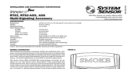
insTaLLaTiOn and mainTenanCe insTrUCTiOns rTs2 aOs aOs accessory 3825 Ohio Avenue St Charles Illinois 60174 FAX 630 377 6495 Voltage Requirements Standby Trouble Alarm w o strobe Alarm with strobe Distance x 5.3 H x 1.6 D 12.2cm W x 11.9 cm H x 3.8 cm D lb 160 g VDC mA max mA max mA max mA max terminal 14 AWG to 22 AWG wire Feet From Duct Smoke Detector dBA at ten feet to 140 10 to 60 relative humidity non condensing 268 and ULC S529 02 1 This manual should be left with the owner user of this equipment infOrmaTiOn National Fire Protection Association NFPA has published codes stan and recommended practices for the installation and use of this product is recommended that the installer be familiar with theses requirements with codes and any special requirements of the local authority having juris For further information consult NFPA 72 and 90A requirements System Sensor RTS2 and RTS2 AOS multi signaling accessories are de for use with System Sensor InnovairFlex 4 wire conventional duct detectors only The accessory has two bicolored LEDs that indicate the status of up to two connected duct smoke detectors The key switch the unit can be used to select a connected duct detector sensor either sen 1 or sensor 2 and the selected sensor can be tested or both sensors can reset simultaneously using the test reset button LED status indications Standby green blink Trouble amber Maintenance amber blink Alarm red the key switch selected there is also the capability of obtaining a sen measurement of the selected sensor using the SENS RDR sensitivity sold separately feaTUres Of The rTs2 and rTs2 aOs inCLUde Standby Green Blink Trouble Amber Maintenance Amber Blink Alarm Red LEDs to indicate detector status Keyswitch to select desired sensor enable test reset button and reading Test reset button Sensitivity reading ability with SENS RDR sold separately Selectable continuous or temporal tone AOS Add On Strobe included on RTS2 AOS model Provisions for single or double gang box mounting Ability to discretely monitor two sensors when duct smoke detectors configured in a 2 to 1 set up See InnovairFlex duct smoke detector for reference RTS2 or RTS2 AOS Multi Signaling Accessory Mounting Hardware Kit Contains 2 sets of mounting screws and 1 tam resistant outer cover mounting screw 2 Add On Strobe SEPERATELY or on RTS2 AOS JUMPER for Continuous pattern READER SWITCH 3 Wiring diagram COVER SCREW TERMINALS the mounting plate Secure the mounting plate to a single or double gang electrical box with mounting screws provided Note If mounting to a single gang box the Strobe AOS must be removed prior to mounting To remove the squeeze opposing sides lightly next to arrows and slide vertically If applicable install the AOS onto the mounting plate as shown in Figure 2 the RTS AOS includes the AOS installation per ULC S524 02 sounder RTS2 accessory provides the option of sounding a continuous or temporal The RTS2 will default to sound in a temporal pattern For a continu pattern remove the jumper located just to the right of the text on mounting plate as shown in Figure 2 the RTS2 as shown in Figure 3 for InnovairFlex 4 wire conventional duct detectors Limit wire runs to 25 ohms or less per interconnecting wire If polarity of Acc and Acc are reversed an Amber LED on sensor of the duct smoke detector power board will exist indicating a trouble One RTS2 can be wired to only one InnovairFlex power board If Aux and Aux wires are reversed the strobe and sounder will the Outer Cover the outer cover on the mounting plate by sliding the outer cover over upper tabs of the mounting plate as shown in Figures 4 and 5 the outer cover mounting screw located at the bottom of the device The mounting screw can be replaced with the provided tamper resistant screw if desired function If polarity of Acc and Acc are reversed Amber LED on sensor 2 of the duct smoke detector board will exist indicating a trouble condition 4 5 green will blink every 5 seconds whenever the duct smoke is receiving power The amber LED is lit when the duct detector sensor is missing or the detector cover is removed The delay indicate a trouble condition once the cover is removed depends on the dip setting on the duct smoke detector power board An LED with amber every 5 seconds indicates that the sensor is in which in that the sensor needs to be cleaned or replaced See Table 1 LED Status for a detailed list of indications The TesT reseT sensiTiviTY OperaTiOn the key and turn to select either sensor 1 or 2 This will enable the sensor to be tested reset or sensitivity read Note all test reset sen functions can be initiated with the outer cover installed or directly on mounting plate fUnCTiOn the desired sensor selected by the key press and hold the Test Reset but for 2 seconds If the sensor is within its sensitivity limits the device will within the next 3 seconds The RTS2 will not initiate a test condition if trouble exists on D4120 indiCaTiOn the Test Reset button has been pressed the red alarm LED will illumi and the horn will sound within 5 seconds If an AOS add on strobe is it will flash fUnCTiOn is a common function to both sensors Press and release the Test Reset The red alarm LED should turn off on both sensor LEDs and the horn cease sounding The strobe will cease flashing if optioned The current status will be indicated See Table 1 Note the key switch must still be for one of the sensors in order for the reset function to be enabled fUnCTiOn the key is installed and sensor 1 or 2 is selected the selected sensor can be read via a SENS RDR sold separately Select the desired sensor with the key Press the test button on the SENS RDR should appear on the display Hold the SENS RDR up to the oval indentation on the mounting plate or cover if installed Within 10 seconds the sensor sensitivity will be The TesT reseT sensiTiviTY OperaTiOn the key switch is returned to the neutral vertical position and the Test Reset button will be disabled 1 Led sTaTUs indiCaTiOns blink off blink blink Amber Red Error long blink Please note that the mode of the LEDs on the RTS2 represent the mode of the sensors connected to the InnovairFlex duct power board Refer to the InnovairFlex installation and maitenance instructions for LED Status details infOrmaTiOn Accessory Accessory Strobe Strobe dUCT smOke deTeCTOrs Listed Photoelectric Duct Detector Watertight Duct Detector Power Board Only Photoelectric Sensor aCCessOries Listed Test Reset Station Listed Listed Remote Test Station Annunciator Annunciator Alarm Reader sounder or sounder strobe combination will not op