System Sensor RTS151KEY Manual

File Preview
Click below to download for free
Click below to download for free
File Data
| Name | system-sensor-rts151key-manual-7289165430.pdf |
|---|---|
| Type | |
| Size | 1.46 MB |
| Downloads |
Text Preview
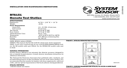
I Ohio Avenue St Charles Illinois 60174 Fax 630.377.6495 AND MAINTENANCE INSTRUCTIONS Test Station Requirements LED Green LED Red Response Time RTS151KEY A replaces RTS451KEY H 2.75 W 1.8 D Lbs 35 VDC 12 mA maximum 32 VDC 12 mA maximum seconds maximum to 60 14 to 140 relative humidity noncondensing Max FM CE This manual shall be left with the owner user of this equipment A test coil is required only for use with D2 DNR DH400 DH500 mod D2 models order part DCOIL For DH400 500 models order part Coil INFORMATION System Sensor RTS151KEY A is an automatic fire detector accessory de to test remotely located duct and beam detectors For 4 wire detec the RTS151KEY A features a multi colored LED that alternates between green and red Green indicates power and that the detector board is place Red indicates alarm For 2 wire detectors the LED will show red for Consult the detector installation instructions for additional informa National Fire Protection Association has published codes standards and practices for the installation and use of this product It is rec that the installer be familiar with these requirements with local and any special requirements of the local authority having jurisdiction CONTENTS RTS151KEY A remote test station screw pack 2 mounting screws Keys Function the key and turn clockwise to the position Indication the key in the position some time will elapse 40 seconds maxi depending on the detector type before the alarm indicating LED will red Function the key counterclockwise to the position and hold The LED turn off Then turn the key back to the position and re The RTS151KEY A is capable of resetting only certain models of detec Refer to the detector installation instructions for additional information Instructions the appropriate detector installation instructions for the applicable diagram The RTS151KEY A mounts to a single gang box 2 1 2 mini depth or directly to the wall or ceiling Canadian applications the RTS151KEY A is intended to be located in the room as the smoke detector and within 60 feet of the unit 1 RTS151KEY A 2 WIRING DIAGRAM FOR RTS151KEY A TO D4120 4 WIRE SMOKE DETECTOR OUT OUT TEST RESET NO C Sup contacts cannot be used if they are wired to control panel 3 WIRING DIAGRAM FOR RTS151KEY A TO DNR 2 WIRE DUCT DETECTOR WITH REMOTE TEST CAPABLE HEAD LED LED COIL COIL CONV ONLY 4 WIRING DIAGRAM FOR RTS151KEY A TO D2 2 WIRE DUCT SMOKE DETECTOR RED REMOTE STATION TEST COIL TEST COIL VDC POWER USER VDC POWER USER VAC 10 WAVE RECTIFIED POWER BE USED VAC 10 WAVE RECTIFIED POWER BE USED RED REMOTE STATION IN OUT RA RA RTS 1 AUX POWER LOCATED AT DUCT DETECTOR 2 AUX POWER LOCATED TEST STATION THE USE OF THE RTS151KEY A REQUIRES THE INSTALLATION OF ACCESSORY COIL DCOIL SOLD SEPARATELY TEST COIL TEST COIL IN OUT RA RA RTS 5 WIRING DIAGRAM FOR RTS151KEY A TO DH100ACDC DUCT SMOKE DETECTOR 6 WIRING DIAGRAM FOR RTS151KEY A TO DH100 2 WIRE SMOKE DETECTOR Terminal 6 of the RTS151KEY A is not used when wired to a 2 wire detector Connection LED Alarm Sup contacts cannot used if they are to control panel LED Reset Out Signal Power N O COM Power Signal Power N O COM Power 7 WIRING DIAGRAM FOR RTS151KEY A TO DH400ACDC DUCT DETECTOR 8 WIRING DIAGRAM FOR RTS151KEY A TO BEAM1224 SMOKE DETECTOR LED Alarm Sup contacts be used if are wired to panel LED ALARM OUT LED ALARM INPUT INPUT YELLOW LED TROUBLE OUTPUT Sensor warrants its enclosed product to be free from defects in materials and under normal use and service for a period of three years from date of System Sensor makes no other express warranty for the enclosed product agent representative dealer or employee of the Company has the authority to in or alter the obligations or limitations of this Warranty The Company obligation this Warranty shall be limited to the replacement of any part of the product which is to be defective in materials or workmanship under normal use and service during three year period commencing with the date of manufacture After phoning System toll free number 800 SENSOR2 736 7672 for a Return Authorization number RTS151KEY A CAN BE USED WITH INTELLIGENT BEAM DETECTOR PRODUCTS INTELLIGENT BEAM DETECTOR MANUAL FOR ADDITIONAL INSTRUCTIONS LIMITED WARRANTY defective units postage prepaid to Honeywell 12220 Rojas Drive Suite 700 El Paso 79936 USA Please include a note describing the malfunction and suspected cause failure The Company shall not be obligated to replace units which are found to be because of damage unreasonable use modifications or alterations occurring the date of manufacture In no case shall the Company be liable for any consequen or incidental damages for breach of this or any other Warranty expressed or implied even if the loss or damage is caused by the Company negligence or fault states do not allow the exclusion or limitation of incidental or consequential dam so the above limitation or exclusion may not apply to you This Warranty gives you legal rights and you may also have other rights which vary from state to state System Sensor 06 10