System Sensor SA Ceiling Strobes and Horn Strobes Manual

File Preview
Click below to download for free
Click below to download for free
File Data
| Name | system-sensor-sa-ceiling-strobes-and-horn-strobes-manual-6354271980.pdf |
|---|---|
| Type | |
| Size | 744.63 KB |
| Downloads |
Text Preview
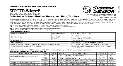
INSTALLATION AND MAINTENANCE Ceiling Mount Series and Horn Strobes use with the following models volt SC2415W SC241575W SC2430W SC2475W SC2495W SC24115W SC24177W 24 volt PC2415W PC241575W PC2430W PC2475W PC2495W PC24115W PC24177W Horn units will operate on walk tests with on time durations of 25 sec or greater Description designed to meet the requirements of most agencies Alarm Code UL FM CSFM MEA Also check with Alarm System Considerations and Non Temporal Coded Signals other than those used for evacuation purposes do is accomplished by interrupting a steady sound in Sec Sec Sec Sec Sec Sec Supply Considerations typically supply DC filtered voltage or FWR full Sizes drop Generally for purposes of determining the only 2 volts drop The same devices using 18 AWG 1A Current Draw Measurements RMS limits This does not include the 80 low Max Operating Strobe RMS Max Operating Strobe RMS 1B Horn Sound Measurements dBA Horn Tones Hz Interrupted Hz Interrupted Hz Interrupted Hz Interrupted Hz Interrupted Hz Interrupted Hz Interrupted Hz Interrupted 1C Horn Current Draw Measurements RMS Horn Tones VDC VFWR 1D 24V DC Horn Strobe Current Draw mA RMS Volume Volume Volume Volume Setting Hz Hz Hz Hz 1E Positioning for Maximum Brightness For maximum brightness unit must be mounted Operation Non Synchronized Devices 2A Any combination of models powered by a circuit ONLY Selections set for high volume temporal code and electrome When powered from FWR supply tones will be or low volume may