System Sensor SA P24 and S24 Models Manual

File Preview
Click below to download for free
Click below to download for free
File Data
| Name | system-sensor-sa-p24-and-s24-models-manual-7809653412.pdf |
|---|---|
| Type | |
| Size | 767.58 KB |
| Downloads |
Text Preview
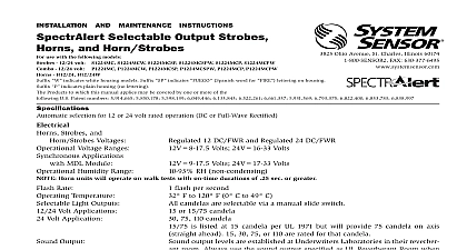
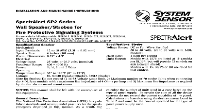
INSTALLATION AND MAINTENANCE INSTRUCTIONS Strobe and use with the following 24 volt models colors for Red for Amber for Green for Blue suffix indicates no markings on the housing add suffix for white housing models Products to which this manual applies may be covered by one or more of the following Patent numbers 5,914,665 5,850,178 5,593,569 5,598,139 6,049,446 6,133,843 S2475ALP S2475GLP S2475BLP P2475ALP P2475GLP P2475BLP Range or Full Wave Rectified Ohio Avenue St Charles Illinois 60174 FAX 630 377 6495 and Horn Strobes 24 volt models 20 to 30 volts models 21 to 30 volts MDL module Combo unit will operate on walk tests with on time durations of 1 sec or greater Flash Per Second F to 120 F 0 C to 49 C candela output levels are established at Underwriters Laboratories in their reverberant room Always use the output specified as UL Reverberant Room when comparing products S4011 Horn Strobe UL S3593 Strobe Rate Temperature Output Output Description SpectrAlert series notification appliances are designed to meet the of NFPA The National Fire Alarm Code and UL Also check your local Authority Having Jurisdiction for other codes or standards may apply SpectrAlert S2475XXX Series Strobe and P2475XXX Series style can be installed in systems using 24 volt panels having DC or rectified FWR power supplies The models can also be installed systems requiring synchronization module MDL required or systems do not require synchronization no module required This manual shall be left with the owner user of this equipment Alarm System Considerations and Non Temporal Coded Signals American National Standards Institute and the National Fire Alarm require that all horns used for building evacuation installed after July 1996 must produce Temporal Coded Signals other than those used for evacuation purposes do not have to pro the Temporal Coded Signal Temporal coding is accomplished by inter a steady sound in the following manner Sec Sec Sec Sec Sec Sec Supply Considerations typically supply DC filtered voltage or FWR full wave rectified The system design engineer must calculate the number of units in a zone based on the type of panel supply Be certain the sum of the device currents do not exceed the current capability of the panel are based on using the device current found in the subsequent and must be the current specified for the type of panel power sup used Sizes designer must be sure that the last device on the circuit has sufficient to operate the device within its rated voltage When calculating voltage available to the last device it is necessary to consider the volt drop due to the resistance of the wire The thicker the wire the less voltage drop Generally for purposes of determining the wire size nec for the system it is best to consider all of the devices as the end of the supply circuit simulates case wire size resistance AWG solid AWG solid AWG solid AWG solid 8 ohms 1,000 ft 5 ohms 1,000 ft 3 ohms 1,000 ft 2 ohms 1,000 ft Assume you have 10 devices on a zone and each requires 50 average and 2000 Ft of 14 AWG wiring total length outgoing The voltage at the end of the loop is 0.050 amps per device x devices x 3 ohms 1,000 ft x 2000 ft 3 volts drop same number of devices using 12 AWG wire will produce only 2 volts The same devices using 18 AWG wire will produce 8 volts drop your panel manufacturer specifications as well as SpectrAlert voltage range to determine acceptable voltage drop If class wiring is installed the wire length may be up to 4 times single wire length in this calculation Draws CURRENT mA CURRENT mA RUSH CURRENT mA Models Models Models FWR DC FWR DC FWR 220 140 191 115 174 FWR DC FWR DC FWR 560 450 570 420 620 FWR DC FWR DC FWR 230 220 290 290 370 Hz CURRENT mA Models FWR DC FWR DC FWR 241 165 209 144 200 238 163 211 145 202 232 153 204 132 189 232 154 204 132 190 246 168 214 152 207 242 167 217 150 210 234 157 206 136 193 232 156 205 137 195 Output Guide Reverberant Room dBA volts DC dBA 10 ft volts DC Volume Volume Volume Volume Hz Interrupted Hz Interrupted Hz Interrupted Hz Interrupted Selections are factory set for high volume temporal code and electromechan tone tones may be selected using the jumper plugs located on printed circuit board With the jumper offset the tone is the sound With the jumper in place the tone is 3 kHz sound coding or Non Temporal coding can be selected using jumper plugs located on the printed circuit board With the offset the tone pattern is the Temporal Coded Signal the jumper in place the Non Temporal code continuous is active Operation Non Synchronized Devices 1A Any combination of models powered by a 2 wire circuit ONLY When powered from FWR supply the tones will be modulated on and off by 120Hz causing the tones to sound dif from DC power Volume or low volume may be selected using the jumper plugs on the printed circuit board With the jumper in place sound output level is the high level With the jumper offset sound output level is the low level The low volume setting NOT be used when the device is powered from a 12 volt Always power down devices before setting jumpers 1B Horns and strobes powered in tandem Supply power must be continuous for proper operation OPERATION COMBO NEXT OR INSTALLED MODULE PREVIOUS 2A Any combination of models powered by a 4 wire circuit provide independent horn and strobe operation Remove facto installed jumpers see Figure 2B Strobes must be powered continuously for horn operation 2B Horns and strobes powered independently Horn oper on coded power supply Strobes must be powered continuously for horn operation OPERATION AND STROBE INSTALLED WIRES REMOVED NEXT OR NEXT OR STROBES MUST POWERED CONTINUOUSLY HORN OPERATION MODULE PREVIOUS wire as shown for of connection NOT allow stripped wire to extend beyond switch DO NOT loop wires 3 Removal of horns and strobes from mounting plates remove units from mounting plates insert Quick Click Removal Tool as shown to unlock snap While in Removal Tool to release the snap pull back on the horn strobe Hinge the horn strobe module the Locking Rib and lift the horn strobe away from the mounting plate SNAP LEVER REMOVAL TOOL SLOT refer to insert for the Limitations of Fire Alarm Systems Limitations of Horn Strobes horn strobe or strobe will not work without power The gets its power from the fire securi