System Sensor SA SP2C Models Manual

File Preview
Click below to download for free
Click below to download for free
File Data
| Name | system-sensor-sa-sp2c-models-manual-9578643120.pdf |
|---|---|
| Type | |
| Size | 785.99 KB |
| Downloads |
Text Preview
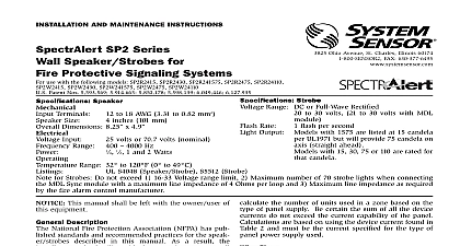
INSTALLATION AND MAINTENANCE INSTRUCTIONS SP2C Series Mount Speaker Strobes for Protective Signaling Systems use with the following models SP2C2415 SP2C241575 SP2C2430 SP2C2495 SP2C24115 SP2C24177 Patent Nos 5,850,178 5,598,139 6,049,446 6,057,778 D424465 5,931,569 6,623,143 3825 Ohio Avenue St Charles Illinois 60174 FAX 630 377 6495 to 18 AWG 3.31 to 0.82 mm2 inches 101 mm diameter 173 mm Terminals Size Dimensions Supervisory Speaker Humidity Range 10 93 RH non condensing Strobes Voltage Range 16 Volts Applications with MDL Module 24 DC FWR Volts VDC Rate Output Output Flash Per Second Models with 15 only in the model number are at 15 candela Models with 1575 in the model number are at 15 candela per UL 1971 but will pro 75 candela on axis straight down Models with 30 75 95 115 177 are for that are established at Sound output Laboratories in their reverberant Always use the sound output specified as UL Room when comparing products S5512 Strobe UL S4048 Speaker Strobe The SP2C Series is suitable for dry and humid environments Not suitable for use in air handling spaces for Strobes Do not exceed 1 16 33 Voltage range limit 2 Maximum number of 70 strobe lights when connecting the MDL module with a maximum line impedance of 4 Ohms per loop and 3 Maximum line impedance as required by the fire alarm manufacturer This manual shall be left with the owner user of this Description National Fire Protection Association NFPA has published and recommended practices for the speaker strobes in this manual As a result the installer must be famil with these requirements as well as all local codes and special of the authority having jurisdiction SpectrAlert SP2C series ceiling mount speaker strobe can be with distribution amplifiers having an output voltage of 25 volts or 70.7 volts speakers operate at any one of four input power levels The sound level is selected at the time of installation but can changed if necessary speaker is also equipped with a capacitive input to allow for supervision SpectrAlert SP2C series ceiling mount strobe can be installed systems using 24 volt panels having DC or full wave rectified power supplies The strobes can also be installed in appli requiring synchronization MDL required or applications do not require synchronization no module required SpectrAlert SP2C series ceiling mount speaker strobes are to meet the requirements of most agencies governing devices including NFPA The National Fire Alarm Code CSFM MEA Also check with your local Authority Having for other codes or standards that may apply Supply Considerations For Strobes typically supply DC filtered voltage or FWR full rectified voltage The system design engineer must cal the number of units used in a zone based on the of panel supply Be certain the sum of all the device currents not exceed the current capability of the panel Calculations are on using the device current found in Table 2 and must be current specified for the type of panel power supply used Sizes designer must be sure that the last device on the circuit has voltage to operate the device within its rated voltage calculating the voltage available to the last device it is to consider the voltage drop due to the resistance of the The thicker the wire the less the voltage drop Generally for of determining the wire size necessary for the system is best to consider all of the devices as on the end of supply circuit simulates case wire size resistance AWG solid AWG solid AWG solid AWG solid 8 ohms 1,000 ft 5 ohms 1,000 ft 3 ohms 1,000 ft 2 ohms 1,000 ft If class wiring is installed the wire length may be up to times the single wire length in this calculation Connect the speaker strobe as shown in Figure 1 Keep in mind even though the speaker and strobe are a single mechani unit they are electrically independent and require separate sources Do NOT loop electrical wiring under terminal screws connecting the device to the control panel must broken at the device terminal connection in order to electrical supervision 2 Voltage and Power Selection 1 Sound levels for each transformer power tap W 1 W 1 2 W 1 4 W 10 ft Assume you have 10 devices on a zone and each 50 mA average and 2000 Ft of 14 AWG wiring length outgoing return The voltage at the end the loop is 0.050 amps per device devices ohms ft ft 3 volts drop same number of devices using 12 AWG wire will produce only volts drop The same devices using 18 AWG wire will produce volts drop Consult your panel manufacturer specifications as as SpectrAlert operating voltage range to determine accept voltage drop wiring must be installed in compliance with the National Code NEC and applicable local codes as well as requirements of the authority having jurisdiction using proper wire size This also includes all applicable NFPA ANSI UL 1480 UL 1971 and NEC 760 1 Electrical connections FROM NEXT OR EOL FROM SUPPLY NEXT OR EOL Supply power for strobe must be continuous for proper operation 2 Current draw of strobes All strobes were only tested at the 16 33 Volt FWR limits This does not include the 80 low end 110 high end voltage limits Max Operating Strobe Max Operatng Strobe RMS RMS No 4 Positioning for maximum brightness For maximum brightness unit must be mounted with angles as shown See Figure 2 as an example of how to select a 1 4 Watt when a 25 volt amplifier is being used Notice that header SW1 has two shunts One shunt is used to either 25 or 70.7 volts input The other shunt is to select input power of 1 4 1 2 1 or 2 Watts Table 1 the UL reverberant and anechoic output sound lev for each power tap on the SP2C series ceiling mount levels exceeding 130 rated signal voltage can dam the speaker Consequently an incorrect tap connection cause speaker damage This means that if a 25V tap is when a 70.7V amplifier is being used speaker damage result Therefore be sure to select the proper taps for the voltage input power level combination being used SP2C series ceiling mount speaker strobe can be flush on a 4 4 21 8 back box Use two 8 32 13 4 pan screws to attach the speaker to the back box See Fig 3 3 Flush mount back box Any combination of 4 box and extension ring may exceed a depth of 35 8 refer to insert for the Limitations of Fire Alarm Systems Limitations of Ceiling Mount Speaker Strobes either of the voltage select or power select shunts is not plugged into of the appropriate option positions the speaker will not sound and will be no trouble indication at the panel Always make sure that the speakers are tested after installation per NFPA regulations speaker may not be heard The loudness of the speaker meets or the current Underwriters Laboratories standards However the may not attract the attention of a sound sleeper or one who has used drugs or has been drinking alcoholic beverages The speaker not be heard if it is placed on a dif