System Sensor SA SP2R1224MC and SP2W1224MC Manual

File Preview
Click below to download for free
Click below to download for free
File Data
| Name | system-sensor-sa-sp2r1224mc-and-sp2w1224mc-manual-0591236847.pdf |
|---|---|
| Type | |
| Size | 1.12 MB |
| Downloads |
Text Preview
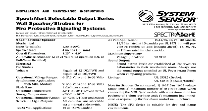
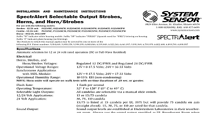
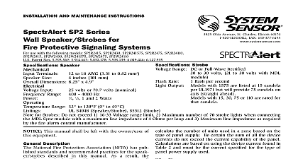
INSTALLATION AND MAINTENANCE INSTRUCTIONS Selectable Output Series Speaker Strobes for Protective Signaling Systems Speaker 12 DC FWR and 8 17.5 10 candelas are selectable output levels are established at Underwriters models SP2R1224MC SP2W1224MC and SP2R1224MCP incorporate a new patent pending voltage booster design that has a more consistent flash bulb over the range of candela selections The benefit to the customer is a high quality strobe device Description the requirements of most agencies governing these including NFPA ADA The National Fire Alarm Having Jurisdiction for other codes or standards that amplifiers having an output voltage of either power supplies The strobes can also be installed Supply Considerations For Strobes typically supply DC filtered voltage or FWR full Sizes drop Generally for purposes of determining the Approximately Approximately Approximately Approximately Assume you have 10 devices on a zone and total length outgoing return The voltage at the only 2 volts drop The same devices using 18 AWG wiring must be installed in compliance with the Na using the proper wire size This also includes all NFPA Standards ANSI UL 1480 UL 1971 and Connect mind that even though the speaker and strobe are NOTE Do NOT loop electrical wiring under terminal 1 Electrical connections FROM NEXT OR EOL FROM SUPPLY NEXT OR EOL Supply power for strobe must be continuous for 1 2 Speaker Voltage and Power Selection 1 Sound levels for each transformer power tap 10 ft 10 ft W W W W 1 4 W 75 W 1 4 W 78 W 2 Strobe current draw measurements 12 24 applications limits This does not include the 80 low No Operating RMS Operatng RMS Selections 3 For strobe candela selections adjust slide located on the rear of the product while