System Sensor SAA CHR, CHW, CHSR and CHSW Manual

File Preview
Click below to download for free
Click below to download for free
File Data
| Name | system-sensor-saa-chr-chw-chsr-and-chsw-manual-9316057824.pdf |
|---|---|
| Type | |
| Size | 1.23 MB |
| Downloads |
Text Preview
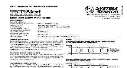
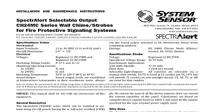
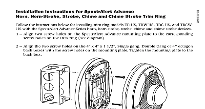
I Ohio Avenue St Charles Illinois 60174 FAX 630 377 6495 AND MAINTENANCE INSTRUCTIONS 142 mm L mm W mm D Output Chimes and Chime Strobes to 18 AWG to 120 0 to 49 to 93 non condensing flash per second 12DC FWR or regulated 24DC FWR1 to 17.5 V 12V nominal or 16 to 33 V 24 nominal to 17.5 V 12V nominal or 16.5 to 33 V 24 V nominal use with the following models CHSR CHSW CHR CHW Specifications Operating Temperature Range Flash Rate Voltage Voltage Range Voltage with MDL3 products will operate at 12 V nominal only for 15 15 75 cd Specifications terminal wire gauge dimensions including lens 5.6 142 mm L mm W mm D dimensions DESCRIPTION and chime strobes are private mode notification appliances used to trained personnel to investigate possible emergency situations and take action SpectrAlert Advance chimes and chime strobes are electri backward compatible with the previous generation of notification appli While they are specifically designed for use on the wall the products listed to be used on the wall or ceiling SpectrAlert products are designed be used in either 12 or 24 volt DC or full wave rectified FWR systems If the MDL3 module may be used in order to provide synchronization This manual shall be left with the owner user of this equipment ALARM SYSTEM CONSIDERATIONS National Fire Alarm Code NFPA 72 requires that all horns used for evacuation installed after July 1 1996 produce temporal coded sig Signals other than those used for evacuation purposes do not have to the temporal coded signal SUPPLY CONSIDERATIONS typically supply DC filtered voltage or FWR full wave rectified volt The system design engineer must calculate the number of units used on loop based on the type of panel supply Be certain the sum of all the device does not exceed the current capability of the panel Calculations are on using the device current found in the subsequent charts and must compatible with the current specified for the panel or power supply used SpectrAlert chimes and chime strobes must be powered from a non power supply SIZES designer must be sure that the last device on the circuit has sufficient to operate the device within its rated voltage When calculating the available to the last device it is necessary to consider the voltage drop to the resistance of the wire The thicker the wire the smaller the volt drop Generally for purposes of determining the wire size necessary for system it is best to consider all of the devices as on the end of supply circuit to simulate worst case For the most accurate voltage drop use the System Sensor voltage drop calculator available on the or CD ROM WIRE RESISTANCE AWG solid 8 ohms 1000 ft AWG solid 5 ohms 1000 ft AWG solid 3 ohms 1000 ft AWG solid 2 ohms 1000 ft If Class A wiring is installed the wire length may be up to twice as as on non fault tolerant circuits SELECTION FOR CHS SERIES MODELS strobe candela selection adjust the slide switch located on the rear of product while watching the viewing window under the reflector on the of the unit Use Table 1 to determine current draw at various candela chime tone settings Tables 2 and 3 can be used to determine strobe light at various viewing angles SpectrAlert products set at 15 and 15 75 candela automatically work either 12V or 24V power supplies The products are not listed for 12V op voltages when set to any other candela settings VOLTS VOLTS INPUT VOLTS INPUT VOLTS 1 CURRENT DRAW mA Second Chime High Second Chime Low Second Chime High Second Chime Low Chime High Chime Low Second Whoop High Second Whoop Low Time Chime Second Chime High Second Chime Low Second Chime High Second Chime Low Chime High Chime Low Second Whoop High Second Whoop Low Time Chime 2 HORIZONTAL PLANE LIGHT DISTRIBUTION WALL AND CEILING APPLICATIONS OF RATED LIGHT OUTPUT 3 VERTICAL PLANE LIGHT DISTRIBUTION WALL APPLICATIONS ANGLE OF RATED LIGHT OUTPUT SELECTION tone setting selection is accomplished by using the rotary switch on the of the product see Table 4 The current draw for various tone settings chimes is listed in Table 5 The sound measurements for various chime settings are shown in Table 6 for chime and chime strobe products 4 CHIME PATTERNS DEFINITIONS 3 4 RATE Second Chime Second Chime Second Chime Second Chime Chime Chime Second Whoop Second Whoop Test Chime OUT 5 CHIME CURRENT DRAW mA VOLTS VOLTS PATTERN Second Chime Second Chime Second Chime Second Chime Chime Chime Second Whoop Second Whoop Test Chime 6 CHIME CHIME STROBE OUTPUT dBA Wiring PATTERN Second Chime Second Chime Second Chime Second Chime Chime Chime Second Whoop Second Whoop Test Chime VOLTS 16 VOLTS 51 56 54 60 1 NON SYNCHRONIZED DEVICES ANY COMBINATION OF POWERED BY A 2 WIRE CIRCUIT 2 SYNCHRONIZED DEVICES ANY COMBINATION OF POWERED BY A 2 WIRE CIRCUIT Wire System Mix of Models for Tandem Wire System Mix of Models for Tandem Wire System Mix of Models for Tandem Wire System Mix of Models for Tandem Module For further information on synchronization see MDL3 panel or power installation manual Module Attach mounting plate to junction box The mounting plate is compatible 4 square single gang double gang and 4 octagon junction boxes using a back box skirt attach the mounting plate to the skirt and then the entire assembly to the junction box Connect field wiring according to terminal definitions If the product is not to be installed at this point use the dust cover to contamination of the wiring terminals of the mounting plate To attach product to mounting plate hook tabs on the product housing the grooves on mounting plate Then swing product into position to the pins on the product with the terminals on the mounting plate su