System Sensor SAA Dual Strobe Expander Plates Manual

File Preview
Click below to download for free
Click below to download for free
File Data
| Name | system-sensor-saa-dual-strobe-expander-plates-manual-9806532714.pdf |
|---|---|
| Type | |
| Size | 2.90 MB |
| Downloads |
Text Preview
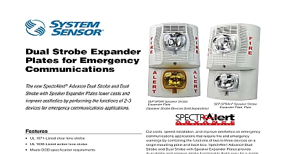
I AND MAINTENANCE INSTRUCTIONS Ohio Avenue St Charles Illinois 60174 FAX 630 377 6495 Strobe and Dual Strobe with Speaker Plates for Emergency Communications SEP SW P Strobe Expander Plate model and SEP BBSW Back Box Skirt model is compatible with SW SWH SW P SWH P SWA SWHA SWA P SWHA P SEP SPSW P Speaker Strobe Expander Plate and SPSEP BBSW Back Box Skirt model is compatible with SPSW SPSWH SPSW P SPSWV SPSWV P SPSWH P only applies to SEP SW and SEP SPSW SPECIFICATIONS Temperature Range Flash Rate Voltage Voltage Range includes fire alarm panels with built in sync Voltage with MDL3 Sync Module terminal wire gauge to 120 0 to 49 to 93 Non condensing flash per second 12VDC FWR or regulated 24DC FWR to 17.5V 12V nominal or 16 to 33V 24V nominal to 17.5V 12V nominal or 16.5 to 33V 24V nominal to 18 AWG Products Products Strobes will operate at 12 V nominal for 15 15 75 candela settings only Switching between ranges is automatic Strobe Expander Plate Amber Lens Standard Candela White ALERT Strobe Expander Plate Standard Candela White Plain Expander Plate Amber Lens Standard Candela White ALERT Expander Plate Standard Candela White Plain Strobe Expander Plate Back Box Skirt White Expander Plate Back Box Skirt White FOR PRODUCTS AND ACCESSORIES P SEP SPSW P SEP BBSW 245mm 130 mm 94mm 257mm 142mm 64mm BOX OPTIONS P x 4 x 1 Single Gang Double Gang 4 Octagon x 4 x 21 8 or deeper P SEP BBSW x 4 x 21 8 Amber lens versions not to be used as a visual public mode alarm notification appliance This manual shall be left with the owner user of this equipment DESCRIPTION SpectrAlert Advance Dual Strobe and Dual Strobe with Speaker Expander for emergency communications use a single device plate to perform the of two to three devices on a back box This combination of multiple on a single plate and back box lowers the overall cost of the installa and improves aesthetics by requiring fewer devices on the wall expander plate provides fast and easy installation first mount the plate a junction box and connect the field wiring to the terminals Then hinge attach the strobe or speaker strobe device with a captured mounting screw complete the installation This product is comparable to existing SpectrAlert mounting plate installations Strobe and Dual Strobe with Speaker Expander Plates are designed to used in 12 or 24 volt DC or FWR full wave rectified systems Clear lens is listed to UL 1971 Listed and CAN ULC S526 07 Signaling Device for Impaired for Public Mode Evacuation Signaling Amber lens strobes UL1638 Listed Visual Signaling Appliances for Private Mode General Util Signaling All SpectrAlert Advance products are suitable for use in syn systems The System Sensor MDL3 module may be used to provide Dual Strobe and Dual Strobe with Speaker Expander Plates are for use on wall and ceiling applications For ceiling mount applications the clear and colored lens strobe meets 1638 light requirements however the device will not meet all of UL1971 plot light requirements DESIGN AND WIRING system designer must make sure that the total current drawn by the de on the loop does not exceed the current capability of the panel supply that the last device on the circuit is operated within its rated voltage current draw information for making these calculations can be found in tables within this manual For convenience and accuracy use the voltage calculator on the System Sensor website www systemsensor com See 1 4 for wiring diagrams and shorting spring information calculating the voltage available to the last device it is necessary to the voltage drop due to the resistance of the wire The thicker the the smaller the voltage drop Wire resistance tables can be obtained electrical handbooks Note that if Class A wiring is installed the wire may be up to twice as long as it would be for circuits that are not tolerant SELECTION the slide switch on the rear of the product to position the desired can setting in the small window on the front of the unit All products meet light output profiles specified in the appropriate UL Standards For amber strobes used for full profile measurement listed candela ratings must reduced in accordance with Table 2 Use Table 1 to determine the current for each candela setting SpectrAlert Advance products set at 15 and 15 75 candela work on ei 12V or 24V power supplies The products are not listed for 12V operating when set to any other candela settings 1 WIRING SEP SPSW P SPEAKER STROBE EXPANDER STANDARD CANDELA WHITE 4 SHORTING SPRING ON SEP SW P STROBE EXPANDER STANDARD CANDELA WHITE SPRING to Next or EoL from Power for Strobe Prior Strobe to Next or EoL to Next or EoL from or Speaker from or Strobe The total number of strobes on a single NAC must not exceed 40 for volt applications or 12 for 12 volt applications Loop resistance on a single should not exceed 120 ohms for 24 volt and 30 ohms for 12 volt systems 2 SHORTING SPRING ON SEP SPSW P SPEAKER STROBE PLATE STANDARD CANDELA WHITE Spring Shorting springs are provided between terminals 2 and 3 and terminals and 6 of the mounting plate to enable wiring checks after the system has wired but prior to installation of the final product These springs will disengage when the product is installed to enable supervision the final system 3 WIRING THE SEP SW P STROBE EXPANDER PLATE CANDELA WHITE from or Strobe from Power for Strobe Prior Strobe to Next or EoL to Next or EoL NOTE A shorting spring is provided between terminals 2 and 3 of the mount plate to enable wiring checks after the system has been wired but prior installation of the final product This spring will automatically disengage the product is installed to enable supervision of the final system 1 CURRENT DRAW mA FOR SEP SW P SEP SPSW P Candela Range Volts 2 CANDELA DERATING FOR SEP SW AND SEP SPSW LENS STROBE Volts Switch Setting Rating 1638 CAN ULC S526 Cd Rating for profile UL 1971 UL1971 is not applicable to mass notification devices but these read were obtained using the measurement procedure specified under UL1971 For more information on current draw light output and sound data reference Speaker Strobe installation manual I56 3935 I56 5250 for and Strobe only installation manual I56 2769 I56 2909 for Canada THE SEP SPSW P SPEAKER STROBE EXPANDER PLATE Attach the speaker strobe expander plate to the junction box as shown in 5 The speaker strobe expander plate is compatible with a 4 x 4 21 8 junction box If using a back box skirt attach the speaker strobe plate to the back box skirt and then attach the entire assembly the junction box see figure 6 Connect the field wiring to the terminals as shown in Figure 1 If the speaker strobe device is not to be installed at this point use the cover to prevent contamination of the speaker strobe expander To attach the speaker strobe device to the speaker strobe expander plate the paint cover then hook the tabs on the product housing into grooves on the strobe plate Swing the speaker strobe device into position to engage the pins on the with the terminals on the speaker strobe expander plate Make that the tabs on the bac