System Sensor SAA PF24 Exitpoint Manual

File Preview
Click below to download for free
Click below to download for free
File Data
| Name | system-sensor-saa-pf24-exitpoint-manual-5367481902.pdf |
|---|---|
| Type | |
| Size | 770.72 KB |
| Downloads |
Text Preview
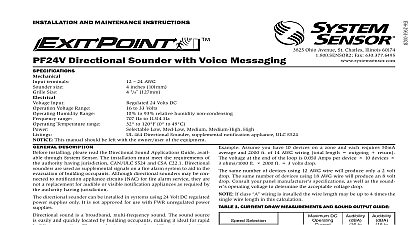
I AND MAINTENANCE INSTRUCTIONS Directional Sounder Description installing please read the Directional Sound must meet the requirements of the authority may be connected to notification appliance circuits making it ideal for rapid building evacuation Sounder incorporates four different pulse patterns approaches the perimeter exit Three additional Supply Considerations for Sounders typically supply DC filtered voltage or FWR full rectified voltage This device is only compatible Sizes wire The thicker the wire the less the voltage drop on the end of the supply circuit simulates Approximately Approximately Approximately Approximately same number of devices using 12 AWG wire will 18 AWG wire will produce an 8 volt drop Consult panel manufacturer specifications as well as the operating voltage to determine the acceptable If 1 Current Draw Measurements and Output Guide Selection DC RMS to 33V to 1 to 2 exit exit exit exit exit Watt Watt Watt Watt Watt Watt Watt Watt Watt Watt Watt Watt Watt Watt Watt Watt Watt Watt Watt Watt 1 2 the Directional Sound Applications Guide for regarding the appropriate mounting locations Settings are made via DIP switches on the back of sounder Switch positions 7 10 are used to select the pattern of the sounder Switch 10 is used to mark are used for egress routing to the perimeter exit positions 5 and 6 are used to select additional sound pulses The additional tone pulse will inserted on every 6th directional sound pulse These area of refuge tone should be used if the directional is marking an area of refuge This tone provides distinct signal indicating that the sounder is not mark an exit If both switches are set to the sounder default to no additional tones In this case only the 2 Additional Tone Selection Guide 5 6 Output Stairs UP Stairs tones setting 4 enables a directional sound device to disabled when used in conjunction with devices switch is in the position the sounder is 3 Enable Disable Function Logic Table 4