System Sensor SAA SPSW-ALERT Manual

File Preview
Click below to download for free
Click below to download for free
File Data
| Name | system-sensor-saa-spsw-alert-manual-7328950146.pdf |
|---|---|
| Type | |
| Size | 1.37 MB |
| Downloads |
Text Preview
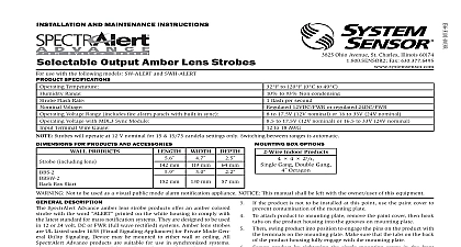
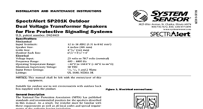
INSTALLATION AND MAINTENANCE INSTRUCTIONS 3825 Ohio Avenue St Charles Illinois 60174 FAX 630 377 6495 Output Amber Lens use with model SPSW ALERT Temperature Range Voltage speakers Supervisory Voltage speakers and strobes Flash Rate Voltage strobes Frequency Range Settings Speakers Voltage Range fire alarm panels with built in sync Voltage with MDL3 Sync Module Terminal Wire Guage to 120 0 to 49 to 93 Non condensing Volts or 70.7 Volts nominal VDC flash per second 12VDC or FWR or regulated 24VDC or FWR to 4000 Hz 1 2 1 2 watts to 17.5V 12V nominal or 16 to 33V 24V nominal to 17.5V 12V nominal or 16.5 to 33V 24V nominal AWG Strobes will operate at 12 V nominal for 15 15 75 candela settings only Switching between ranges is automatic for Speaker Strobes and Accessories Product Speaker Strobe Mount Skirt Width including lens and speaker above finished surface of wall or ceiling Not to be used as a visual public mode alarm notification appliance This manual shall be left with the owner user of this equipment DESCRIPTION SpectrAlert Advance amber lens strobe products offer an amber colored with the word printed on the white housing to comply with latest standard for mass notification systems They are designed to be used 12 or 24 volt DC or FWR full wave rectified systems Amber lens strobes UL Listed under 1638 Visual Signaling Appliances for Private Mode Gen Utility Signaling Device may be mounted to either wall or ceiling All Advance products are suitable for use in synchronized systems System Sensor MDL3 module may be used to provide synchronization speaker portion can be operated with distribution amplifiers having an voltage of either 25 or 70.7 volts With its low total harmonic distor the SpectrAlert Advance SP series offers high fidelity sound output The operate at any one of four input power levels These products are backward compatible with the previous generation of SpectrAlert appliances ALARM SYSTEM CONSIDERATIONS wiring must be installed in compliance with the National Electrical Code and applicable local codes System Sensor recommends installing fire speakers in compliance with NFPA 72 ANSI UL1480 and NEC 760 DESIGN AND WIRING system designer must make sure that the total current drawn by the de on the loop does not exceed the current capability of the panel supply that the last device on the circuit is operated within its rated voltage current draw information for making these calculations can be found in tables within this manual For convenience and accuracy use the voltage calculator on the System Sensor website www systemsensor com or calculating the voltage available to the last device it is necessary to the voltage drop due to the resistance of the wire The thicker the the smaller the voltage drop Wire resistance tables can be obtained electrical handbooks Note that if Class A wiring is installed the wire may be up to twice as long as it would be for circuits that are not fault For 24 volt applications the total number of strobes on a single NAC not exceed 40 with a maximum loop resistance of 120 ohms For 12 volt the total number of strobes must not exceed 12 with a maxi loop resistance of 30 ohms Supply power for strobe must be continuous for proper operation 1 WIRING DIAGRAM 1 SOUND LEVELS FOR EACH TRANSFORMER POWER TAP Reverberant dBA 10 ft Anechoic dBA 10 ft FROM FROM TO SPEAKER EOL TO STROBE EOL WIRING Connect the speaker as shown in Figure 1 NOTE Do not loop electrical wiring under terminal screws Wires con the device to the control panel must be broken at the device connection in order to maintain electrical supervision There are two rotary switches on the back of the product The first switch used to select either 25 or 70.7 volts input for the speaker portion The switch is used to select the input power of 1 4 1 2 1 or 2 watts diagram SPRING Shorting springs are provided between terminals 2 and 3 and between 5 and 6 of the mounting plate to enable wiring checks after the has been wired but prior to installation of the final product These will automatically disengage when the product is installed to enable of the final system 2 SHORTING SPRING levels exceeding 130 rated signal voltage can damage the speaker an incorrect tap connection may cause speaker damage This that if a 25V tap is selected when a 70.7V amplifier is being used damage may result Therefore be sure to select the proper taps for the voltage input power level combination being used SELECTION the slide switch on the rear of the product to position the desired can setting in the small window on the front of the unit For amber lensed used for full profile measurement listed candela ratings must be re in accordance with Table 3 Use Table 2 to determine the current draw each candela setting SpectrAlert products set at 15 and 15 75 candela automatically work either 12V or 24V power supplies The products are not listed for 12V op voltages when set to any other candela settings 2 STROBE CURRENT DRAW MEASUREMENTS SPRINGS 3 SPEAKER WATTAGE AND VOLTAGE SETTINGS Candela Range Current Draw mA Volts Volts NA 3 CANDELA DERATING Switch Setting Rating Cd Rating for 1638 Profile UL1971 is not applicable to mass notification devices but these read were obtained using the measurement procedure specified under UL1971 Attach mounting plate to junction box as shown in Figure 4 The mounting is compatible 4 x 4 x 21 8 junction boxes If using a back box skirt or ring attach the mounting plate to the skirt or trim ring and then attach entire assembly to the junction box see Figures 4 and 5 Connect field wiring to terminals as shown in Figure 1 If the product is not to be installed at this point use the paint cover to contamination of the mounting plate To attach product to mounting plate remove the paint cover then hook on the product housing into the grooves on mounting plate Then swing product into position to engage the pins on the product with terminals on the mounting plate Make sure that the tabs on the back the product housing fully engage with the mounting plate Secure product by tightening the single mounting screw in the front the product housing For tamper resistance the standard captivated screw may be replaced with the enclosed Torx screw 4 WALL MOUNT PRODUCT WITH TRIM RING 5 WALL MOUNT PRODUCT WITH BACK BOX SKIRT Device may be mounted to wall or ceiling refer to insert for the Limitations of Fire Alarm Systems LIMITATIONS OF SPEAKER STROBES speaker and or strobe will not work without power The speaker strobe gets its from the fire security panel monitoring the alarm system If power is cut off for reason the speaker strobe will not provide the desired audio or visual warning make sure that the individual speakers are tested after installation per NFPA speaker may not be heard The loudness of the speaker meets or exceeds the Underwriters Laboratories standards However the speaker may not attract the of a sound sleeper or one who has recently used drugs or has been drinking beverages The speaker may not be heard if it is placed on a different floor from person in hazard or if placed too far away to be heard ove