System Sensor SAA SW-ALERT and SWH-ALERT Manual

File Preview
Click below to download for free
Click below to download for free
File Data
| Name | system-sensor-saa-sw-alert-and-swh-alert-manual-5096874321.pdf |
|---|---|
| Type | |
| Size | 1.27 MB |
| Downloads |
Text Preview
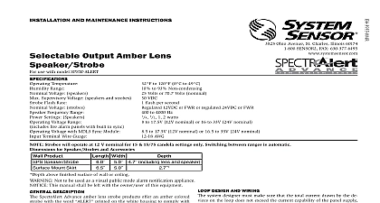
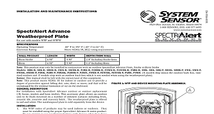
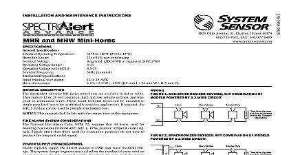
INSTALLATION AND MAINTENANCE INSTRUCTIONS Output Amber Lens Strobes Ohio Avenue St Charles Illinois 60174 Fax 630.377.6495 use with the following models SW ALERT and SWH ALERT SPECIFICATIONS Temperature Range Flash Rate Voltage Voltage Range includes fire alarm panels with built in sync Voltage with MDL3 Sync Module Terminal Wire Gauge to 120 0 to 49 to 93 Non condensing flash per second 12VDC FWR or regulated 24DC FWR to 17.5V 12V nominal or 16 to 33V 24V nominal to 17.5V 12V nominal or 16.5 to 33V 24V nominal to 18 AWG Strobes will operate at 12 V nominal for 15 15 75 candela settings only Switching between ranges is automatic FOR PRODUCTS AND ACCESSORIES PRODUCTS WIDTH MOUNTING BOX OPTIONS Indoor Products 4 21 8 Octagon mm mm mm Gang Double Gang mm mm mm including lens Box Skirt Not to be used as a visual public mode alarm notification appliance NOTICE This manual shall be left with the owner user of this equipment DESCRIPTION SpectrAlert Advance amber lens strobe products offer an amber colored with the word printed on the white housing to comply with latest standard for mass notification systems They are designed to be used 12 or 24 volt DC or FWR full wave rectified systems Amber lens strobes UL Listed under 1638 Visual Signaling Appliances for Private Mode Gen Utility Signaling Device may be mounted to either wall or ceiling All Advance products are suitable for use in synchronized systems System Sensor MDL3 module may be used to provide synchronization DESIGN AND WIRING system designer must make sure that the total current drawn by the de on the loop does not exceed the current capability of the panel supply that the last device on the circuit is operated within its rated voltage current draw information for making these calculations can be found in tables within this manual For convenience and accuracy use the voltage calculator on the System Sensor website www systemsensor com or calculating the voltage available to the last device it is necessary to the voltage drop due to the resistance of the wire The thicker the the smaller the voltage drop Wire resistance tables can be obtained electrical handbooks Note that if Class A wiring is installed the wire may be up to twice as long as it would be for circuits that are not fault SELECTION the slide switch on the rear of the product to position the desired can setting in the small window on the front of the unit For amber lensed used for full profile measurement listed candela ratings must be re in accordance with Table 2 Use Table 1 to determine the current draw each candela setting SpectrAlert products set at 15 and 15 75 candela automatically work either 12V or 24V power supplies The products are not listed for 12V op voltages when set to any other candela settings Attach mounting plate to junction box as shown in Figures 3 and 4 The plate is compatible with 4 square double gang and 4 octa junction boxes If using a back box skirt attach the mounting plate the skirt and then attach the entire assembly to the junction box see 3 and 4 Connect field wiring to terminals as shown in Figure 1 If the product is not to be installed at this point use the paint cover to contamination of the mounting plate To attach product to mounting plate remove the paint cover then hook on the product housing into the grooves on mounting plate Then swing product into position to engage the pins on the product with terminals on the mounting plate Make sure that the tabs on the back the product housing fully engage with the mounting plate Secure product by tightening the single mounting screw in the front the product housing For tamper resistance the standard captivated screw may be replaced with the enclosed Torx screw 1 WIRING PRODUCT NEXT EOL For 24 volt applications the total number of strobes on a single NAC not exceed 40 with a maximum loop resistance of 120 ohms For 12 volt the total number of strobes must not exceed 12 with a maxi loop resistance of 30 ohms Figure 2 Shorting Spring A shorting spring is provided between terminals 2 and 3 of the mount plate to enable wiring checks after the system has been wired but prior SPRING installation of the final product This spring will automatically disengage the product is installed to enable supervision of the final system 3 SURFACE MOUNTING WITH BACK BOX SKIRT 1 STROBE CURRENT DRAW MA Volts Volts 2 Switch Setting Rating Cd Rating for Profile 1638 UL1971 is not applicable to mass notification devices but these read were obtained using the measurement procedure specified under UL1971 4 RECESSED MOUNTING refer to insert for the Limitations of Fire Alarm Systems A0377 00 LIMITATIONS OF HORN STROBES horn and or strobe will not work without power The horn strobe gets its power from the fire panel monitoring the alarm system If power is cut off for any reason the horn strobe will not the desired audio or visual warning horn may not be heard The loudness of the horn meets or exceeds current Underwriters standards However the horn may not alert a sound sleeper or one who has recently used or has been drinking alcoholic beverages The horn may not be heard if it is placed on a different from the person in hazard or if placed too far away to be heard over the ambient noise such as air conditioners machinery or music appliances that may prevent alert persons from hearing the The horn may not be heard by persons who are hearing impaired signal strobe may not be seen The electronic visual warning signal uses an extremely reliable xe flash tube It flashes at least once every second The strobe must not be installed in direct sunlight areas of high light intensity over 60 foot candles where the visual flash might be disregarded or not The strobe may not be seen by the visually impaired signal strobe may cause seizures Individuals who have positive photoic response to visual stimuli seizures such as persons with epilepsy should avoid prolonged exposure to environments in strobe signals including this strobe are activated signal strobe cannot operate from coded power supplies Coded power supplies produce interrupted The strobe must have an uninterrupted source of power in order to operate correctly System recommends that the horn and signal strobe always be used in combination so that the risks any of the above limitations are minimized LIMITED WARRANTY Sensor warrants its enclosed product to be free from defects in materials and workmanship normal use and service for a period of three years from date of manufacture System Sensor no other express warranty for this product No agent representative dealer or employee of Company has the authority to increase or alter the obligations or limitations of this Warranty The obligation of this Warranty shall be limited to the replacement of any part of the product is found to be defective in materials or workmanship under normal use and service during the year period commencing with the date of manufacture After phoning System Sensor toll free 800 SENSOR2 736 7672 for a Return Authorization number send defective units postage to Honeywell 12220 Rojas Drive Suite 700 El Paso TX 79936 USA Please include a note the malfunction and suspected cause of failure The Company shall not be obligated to units which are found to be defective because of damage unreasonable use modifications