System Sensor SC-6 Manual

File Preview
Click below to download for free
Click below to download for free
File Data
| Name | system-sensor-sc-6-manual-1462875039.pdf |
|---|---|
| Type | |
| Size | 1.57 MB |
| Downloads |
Text Preview
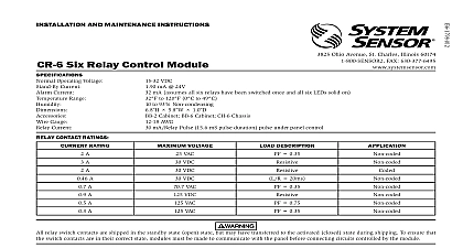
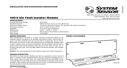
INSTALLATION AND MAINTENANCE INSTRUCTIONS Ohio Avenue St Charles Illinois 60174 FAX 630 377 6495 Six Supervised Control Module Operating Voltage Current Current Range Gauge NAC Circuit Line Loss Rating Per Circuit Speakers Current Ratings CONTACT RATINGS RATING mA 24V mA assumes all six relays have been switched once and all six LEDs solid on to 120 0 to 49 10 to 55 For EN54 application only to 93 Non condensing x 5.8 x 1.25 Chassis BB 2 Cabinet BB 6 Cabinet AWG VDC 70.7VAC 50W 25VAC class B wiring system 3A class A wiring system 2A VOLTAGE DESCRIPTION A A A A A A A A VAC VDC VDC VDC VAC VDC VAC VAC 20ms 0.35 0.35 0.75 0.35 1 SHORT CIRCUIT PROTECTION UL 864 9TH EDITION REQUIREMENTS TO USERS INSTALLERS AUTHORITIES HAVING JURISDICTION AND OTHER INVOLVED PARTIES product incorporates field programmable software In order for the product to comply with requirements in the Standard for Control Units and for Fire Alarm Systems UL 864 certain programming features or options must be limited to specific values or not used at all as indicated below FEATURE OR OPTION SETTINGS PERMITTED IN UL 864 short circuit protection a single power supply is shared multiple NACs or Disable short protection short circuit protection when a single power supply is by multiple NACs Short circuit protection can be disabled when a power supply is not shared by multiple NACs IN 864 Y N INSTALLING information is included as a quick reference installation guide Refer to appropriate control panel installation manual for detailed system infor If the modules will be installed in an existing operational system the operator and local authority that the system will be temporarily of service Disconnect the power to the control panel before installing the This system contains static sensitive components Always ground with a proper wrist strap before handling any circuits so that static are removed from the body The housing cabinet should be metallic suitably grounded This manual should be left with the owner user of this equipment DESCRIPTION SC 6 Six Supervised Control Module is intended for use in an intelligent system Each module is intended for switching applications involving DC or audio which require wiring supervision A common SLC input is for all modules Each module has its own address A pair of rotary code is used to set the address of the first module from 01 to 94 The re modules are automatically assigned to the next five higher addresses are included for disabling a maximum of three unused modules release the addresses to be used elsewhere Each module also has panel green LED indicators The panel can cause the LEDs to blink latch or latch off order to synchronize strobes horn strobes and speaker strobes a SYNC 1 card sold separately must be used with the SC 6 See the SYNC 1 manual for details on how to install module has terminals for connection to an external supply circuit for devices on its NAC supply must be power limited and its voltage current limits must be at below those specified is a short circuit protection monitor for each module This is provided to the external power supply against short circuit conditions on the NAC 2 BB 2 CABINET on Board Small shunt in A B select position Large shunts on Enable Power Supply Monitors Large shunts on Disable Short Circuit Protection Large shunts on Sync Generator in Class B position remove shunt for Class A 1 Terminal 11 4 32mm off Large Shunts Machine Screws Short Power Jumpers Small Shunts Nuts Long Power Supply Jumper 47k Ohm of Line EOL Relay REQUIREMENTS ensure proper operation this module shall be connected to a listed compat control panel are descriptions of the SC 6 mounting frameworks There are two options for SC 6 modules Up to six SC 6 modules can be installed on a CH 6 in a BB 6 cabinet One or two SC 6 modules can be installed in a BB 2 cabinet CH 6 chassis is used to mount SC 6 modules in a BB 6 cabinet It accom up to six SC 6 modules in a single cabinet row three modules wide two modules deep BB 2 cabinet has a built in chassis that will accommodate one or two modules 1 CH 6 CHASSIS front SC 6 module positions of each chassis are offset below the rear SC 6 positions so that all of the status indicators are visible BB 6 cabinet will house the CH 6 chassis with up to six SC 6 modules in on it Refer to cabinet installation documents for dimensions BB 2 cabinet houses one or two SC 6 modules on the internal chassis that part of the cabinet Refer to cabinet installation documents for dimensions STEPS Cabinet Mounting In a clean dry area mount the backbox using the four holes provided in back surface of the cabinet Figure 3 Chassis Installation The CH 6 chassis is mounted in the BB 6 cabinet It is shipped with two screws which are used to fasten the chassis to the back of the cabinet see Figure 4 3 TYPICAL MOUNTING HOLE LOCATIONS 4 MOUNTING THE CH 6 CHASSIS WITH SCREWS BACK OF CABINET BB 2 cabinet comes with the chassis already installed so no mounting necessary Module Installation There are two methods for installing a module in the rear position of a Method one is for installation of a rear module only when no will be installed in front of it Refer to Figure 5 for instructions two is for installation of a rear module when another module be installed in the chassis position in front of it Refer to Figures 6a 6b for method two All necessary screws and standoffs are supplied the modules 5 INSTALLATION OF REAR MODULE ONLY METHOD ONE 6B INSTALLATION OF SC 6 MODULE IN FRONT CHASSIS POSI 1 Insert the bottom of the SC 6 module down into a rear slot on the 2 Carefully swing the upper edge of the board back towards the back of chassis until it touches the two standoffs 3 Align two 4 40 screws with the two standoffs and tighten 4 Address and wire the modules according to the instructions in this steps in Figures 6a and 6b describe and illustrate module installation the rear chassis position and the position in front of it will be filled position installation is possible only if the rear position is filled with module 6A INSTALLATION OF SC 6 MODULE IN A REAR CHASSIS POSI METHOD TWO 1 Insert the bottom edge of the SC 6 module down into a rear slot of chassis 2 Carefully swing the upper edge of the board towards the back of the until it touches the short standoff attached to the chassis 3 Align the long standoff with the short standoff and tighten 1 Insert the bottom edge of the SC 6 module down into a front slot of chassis 2 Carefully swing the upper edge of the board towards the back of the until it touches the 11 4 31.75mm standoffs installed on rear module 3 Align two 4 40 screws with the two standoffs and tighten 4 Address and wire the modules acco