System Sensor Select Series Bases (SPDS901)

File Preview
Click below to download for free
Click below to download for free
File Data
| Name | system-sensor-select-series-bases-spds901-8764501329.pdf |
|---|---|
| Type | |
| Size | 936.36 KB |
| Downloads |
Text Preview
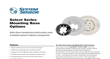
Select Series Base Sensor mounting bases and kits provide a variety installation options for detectors in any application Bases enable quick and secure detector plug in SEMS screws provide easy wiring connection Support for 12 24 AWG provides installation flexibility Multiple base formats meet application requirements Standard white color with ivory and black options UL 268 compliant Mechanical locking feature restricts removal of attached sensor Base Features Pre wired mounting plate simplifies installation Application driven feature sets Sounder bases both UL 268 and UL 464 compliant meet local code and application requirements Sensor offers standard 4 and 6 bases as well as base designs including relay isolator sounder and low sounder options for Select Series detectors standard 4 and 6 bases offer a plug in detector base intended use in intelligent systems with screw terminals provided for power and and remote annunciator connections Communication place over the power and lines The 4 base offers a design while the 6 base provides compatibility with a wider of junction boxes Select Series specialty bases support application driven The bases employ a separate mounting plate installs on various junction box sizes to eliminate unsightly boxes The mounting plate enables pre wiring of all to speed and simplify installation bases B224RB WH B224RB IV provide one form C contact for control of auxiliary functions such as door closure and recall The relay can operate in two different modes short long delay The activation time for the short delay is 60 ms to ms while the activation time for the long delay is 6 sec to 10 sec shunt with pin headers located on the base PC board is used to the delay timing bases B224BI WH B224BI IV allow the Signaling Line SLC loop to operate under fault conditions created from a circuit preventing an entire communication loop from being The base isolates the section of the loop containing the circuit from the remainder of the circuit and automatically when the fault is corrected Select Series sounder and low frequency sounder bases designed for new and existing dwelling unit applications offer maximum flexibility in installation configuration and to meet or exceed UL 268 and UL 464 requirements The Listings 6 bases 7300 1653 0109 Isolator bases 7300 1653 0126 bases 7135 1653 0213 bases 7300 1653 0238 Consult your fire alarm control panel manufacturer for compatibility the addressable model of the sounder base 04 04 2018 Page 1 Series low frequency sounder bases designed to meet the NFPA 72 sleeping requirement to produce a fundamental of 520 Hz 10 with a square or its equivalent Studies show that a frequency centered around 520 Hz is most ideal to wake sleeping occupants those with mild to severe hearing loss B200SR sounder and LF sounder bases are fully compatible with B501BH Series sounder base The device enables users to one of two B501 supported tones Temporal 3 or Continuous through a B200S sounder and LF sounder bases adopt the same address as detector but use a unique device type the loop The Fire Alarm Control Panel can use that address to command individual sounder or a group of to activate The command set the FACP can be tailored to multiple tone outputs allowing selection volume 75 or 85 dBA tone ANSI 3 ANSI Temporal 4 or March Time group In addition some FACPs will custom tone patterns The B200S sounder bases recognize the System synchronization protocol This it to be used as a component of general evacuation signal along with System Sensor AV appliances when to a power supply or FACP output of generating the System Sensor pulses Select Series Bases Specifications B501 IV B501 BL 4.0 10.2 cm B200S IV B200S LF WH B200S LF IV B200SR WH B200SR IV B200SR LF WH B200SR LF IV 6.85 cm B300 6 IV 6.1 155 mm B224BI IV B224RB WH B224RB IV 6.85 17.4 cm B501 IV B501 BL 0.74 18.8 mm B200S IV B200S LF WH B200S LF IV B200SR WH B200SR IV B200SR LF WH B200SR LF IV 1.6 4.1 B300 6 IV 0.76 19 mm B224BI IV B224RB WH B224RB IV 1.61 4.1 cm 0.32 lb 145 gm B200S IV B200SR WH B200SR IV 0.50 lb 227 gm B200S LF IV B200SR LF WH B200SR LF IV Weight 0.6 lb 272 gm B300 6 IV 0.32 lb 145 gm B224RB IV B224BI WH B224BI IV 0.50 lb 227 gm B501 IV B501 BL B224BI WH B224BI IV B224RB WH B224RB IV B300 6 B300 6 IV 18 AWG 0.823 to 12 AWG 3.31 mm B200S IV B200S LF WH B200S LF IV B200SR WH B200SR IV B200SR LF WH B200SR LF IV 14 AWG 12 AWG to applicable sensor Operating Temperature Range using the Base Sensor Cross Reference Chart at to 93 RH non condensing Height sensor Gauge Range Range Specifications B501 IV B501 BL Includes base and detector Voltage Current to 32 VDC Specifications B22RB IV Voltage Current Time to 32 VDC max 1 Short Delay 60 to 100 ms 2 Long Delay 6 to 10 sec ms max coil latching relay Form C contact Rating VAC VDC VDC VDC VAC VDC VAC VAC 20ms 0.35 0.35 0.75 0.35 Time A A A A A A A A 04 04 2018 Page 2 Specifications B300 6 IV Voltage Current to 32 VDC max Specifications B22BI IV Voltage Current Current to 32 VDC max mA max Specifications B200S IV Supply Electrical Ratings to 33 VDC VFWR Supply Current 500 maximum Current to 32 VDC maximum Electrical Ratings Operating Standby Output Volume Volume mA maximum at high volume setting mA maximum at low volume setting than 85 dBA minimum measured in UL reverberant room at 10 feet 24 Volts in tone than 75 dBA minimum measured in UL reverberant room at 10 feet 24 Volts in tone Specifications B200SR IV Supply Electrical Ratings to 33 VDC VFWR Supply Current 500 maximum mA maximum Current Electrical Ratings Operating Standby Output to 32 VDC maximum than 85 dBA minimum measured in UL reverberant room at 10 feet 24 Volts in tone Specifications B200S LF IV Supply Electrical Ratings to 33 VDC VFWR Supply Current 550 maximum VDC Current High volume setting Current Low volume setting mA maximum 33.0 VDC mA maximum 24.0 VDC mA maximum 16.0 VDC mA maximum 33.0 VDC mA maximum 24.0 VDC mA maximum 16.0 VDC Electrical Ratings to 32 VDC Operating Standby Output Volume Volume maximum base only refer to sensor specification than 85 dBA minimum measured in UL reverberant room at 10 feet 24 Volts in tone than 75 dBA minimum measured in UL reverberant room at 10 feet 24 Volts in tone Specifications B200SR LF IV Supply Electrical Ratings to 33 VDC VFWR Supply Current 1 mA maximum VDC Current mA maximum 33.0 VDC mA maximum 24.0 VDC mA maximum 16.0 VDC to 32 VDC Electrical Ratings Operating Standby Output to applicable sensor specification than 85 dBA minimum measured in UL reverberant ro