System Sensor spectralert-chime-not

File Preview
Click below to download for free
Click below to download for free
File Data
| Name | system-sensor-spectralert-chime-not-7416390528.pdf |
|---|---|
| Type | |
| Size | 889.34 KB |
| Downloads |
Text Preview
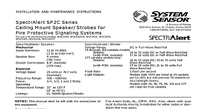
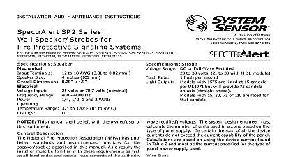
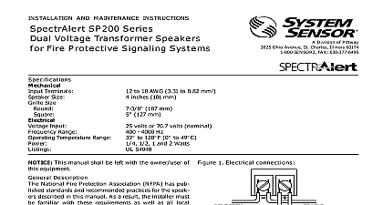
INSTALLATION AND MAINTENANCE INSTRUCTIONS Electronic Chime Sounder use with the following models 12 24 volt CH12 24 suffix for white models SENSOR Division of Pittway 3825 Ohio Avenue St Charles Illinois 60174 FAX 630 377 6495 ert Range Temperature Output or Full Wave Rectified Volts F to 120 F 0 C to 49 C output levels are established at Underwriters Laboratories in their reverberant room Always use the sound out specified as UL Reverberant Room when comparing products 464 Private Mode Description SpectrAlert series notification appliances are designed to meet the of most agencies governing these devices including The National Fire Alarm Code UL FM CSFM MEA Also check your local Authority Having Jurisdiction for other codes or stan that may apply SpectrAlert series can be installed in systems using 12 or 24 volt having DC or full wave rectified FWR power supplies This manual shall be left with the owner user of this equipment Alarm System Considerations and Non Temporal Coded Signals American National Standards Institute and the National Fire Alarm require that all horns used for building evacuation installed after July 1996 must produce Temporal Coded Signals Signals other than those for evacuation purposes do not have to produce the Temporal Coded Supply Considerations typically supply DC filtered voltage or FWR full wave rectified The system design engineer must calculate the number of units in a zone based on the type of panel supply Be certain the sum of the device currents do not exceed the current capability of the panel are based on using the device current found in the subse charts and must be the current specified for the type of panel supply used Sizes designer must be sure that the last device on the circuit has sufficient to operate the device within its rated voltage When calculating voltage available to the last device it is necessary to consider the volt drop due to the resistance of the wire The thicker the wire the less voltage drop Generally for purposes of determining the wire size nec for the system it is best to consider all of the devices as the end of the supply circuit simulates case wire size resistance AWG solid AWG solid AWG solid AWG solid 8 ohms 1,000 ft 5 ohms 1,000 ft 3 ohms 1,000 ft 2 ohms 1,000 ft Assume you have 10 devices on a zone and each requires 50 average and 2000 Ft of 14 AWG wiring total length outgoing re The voltage at the end of the loop is 0.050 amps per device x 10 x 3 ohms 1,000 ft x 2000 ft 3 volts drop If Class A wiring is installed the wire length may be up to 4 times single wire length in this calculation Limitations of Electronic Chimes chime will not work without power The chime gets its power from fire security panel monitoring the alarm system If power is cut off any reason the chime will not provide the desired audio or visual chime may not be heard The loudness of the chime meets or ex current Underwriters Laboratories standards However the chime not alert a sound sleeper or one who has recently used drugs or has drinking alcoholic beverages The chime may not be heard if it is on a different floor from the person in hazard or if placed too far to be heard over the ambient noise such as traffic air conditioners or music appliances that may prevent alert persons from hear the alarm The chime may not be heard by persons who are hearing Limited Warranty Sensor warrants its enclosed electronic chime to be free from de in materials and workmanship under normal use and service for a of three years from date of manufacture System Sensor makes no express warranty for this electronic chime No agent representative or employee of the Company has the authority to increase or alter obligations or limitations of this Warranty The Company obligation this Warranty shall be limited to the repair or replacement of any part of electronic chime which is found to be defective in materials or work under normal use and service during the three year period com with the date of manufacture After phoning System Sensor toll number 800 SENSOR2 736 7672 for a Return Authorization number defective units postage prepaid to System Sensor Repair Depart RA 3825 Ohio Avenue St Charles IL 60174 Please a note describing the malfunction and suspected cause of failure Company shall not be obligated to repair or replace units which are to be defective because of damage unreasonable use modifica or alterations occurring after the date of manufacture In no case the Company be liable for any consequential or incidental damages breach of this or any other Warranty expressed or implied whatsoever if the loss or damage is caused by the Company negligence or fault states do not allow the exclusion or limitation of incidental or conse damages so the above limitation or exclusion may not apply to This Warranty gives you specific legal rights and you may also have rights which vary from state to state System Sensor same number of devices using 12 AWG wire will produce only 2 volts The same devices using 18 AWG wire will produce 8 volts drop Con your panel manufacturer specifications as well as SpectrAlert oper voltage range to determine acceptable voltage drop Selection are factory set for low vloume temporal code and 500 Hz Tones may be selected by making the appropriate on the Dip Switch located on the printed circuit board The set required for the available tone options are as follows Electronic Chime Current Draw current draw varies with tones selected Current ratings per Sensor testing at 12VDC and 24VDC Chime Switch Settings 1 second chime 1 second chime 1 second chime 1 4second chime 1 4second chime 1 4second chime 3 chime 3 chime 3 chime Stroke Chime Stroke Chime Stroke Chime Continuous Temporal 3 Hz Continuous Hz Temporal 3 0 off LOW MED HIGH Chime Tones 1 Second Chime 1 4 Second Chime 3 Chime Stroke Chime 500Hz Mechanical and 3kHz mechanical 500Hz mechanical and 3kHz mechanical second Electronic Chime Sound Output Guide Tone 1.2K Repeating 1 Second Chime 1.0K Repeating 1 Second Chime 0.8K Repeating 1 Second Chime 1.2K Repeating 1 4 Second Chime 1.0K Repeating 1 4 Second Chime 0.8K Repeating 1 4 Second Chime 1.2K Temporal 3 Chime 1.0K Temporal 3 Chime 0.8K Temporal 3 Chime 1.2K Single Stroke Chime 1.0K Single Stroke Chime 0.8K Single Stroke Chime 3.0K Continuous Mechanical 3.0K Temporary Mechanical 0.5K Continuous Mechanical 0.5K Temporary Mechanical Volts Volts Tone 1.2K Repeating 1 Second Chime 1.0K Repeating 1 Second Chime 0.8K Repeating 1 Second Chime 1.2K Repeating 1 4 Second Chime 1.0K Repeating 1 4 Second Chime 0.8K Repeating 1 4 Second Chime 1.2K Triple Stroke Chime 1.0K Triple Stroke Chime 0.8K Triple Stroke Chime 1.2K Single Stroke Chime 1.0K Single Stroke Chime 0.8K Single Stroke Chime 3.0K Continuous Mechanical 3.0K Temporary Mechanical 0.5K Continuous Mechanical 0.5K Temporary Mechanical