System Sensor spectralert-horns and strobes series installation
File Preview
Click below to download for free
Click below to download for free
File Data
| Name | system-sensor-spectralert-horns-and-strobes-series-installation-4153280796.pdf |
|---|---|
| Type | |
| Size | 877.31 KB |
| Downloads |
Text Preview
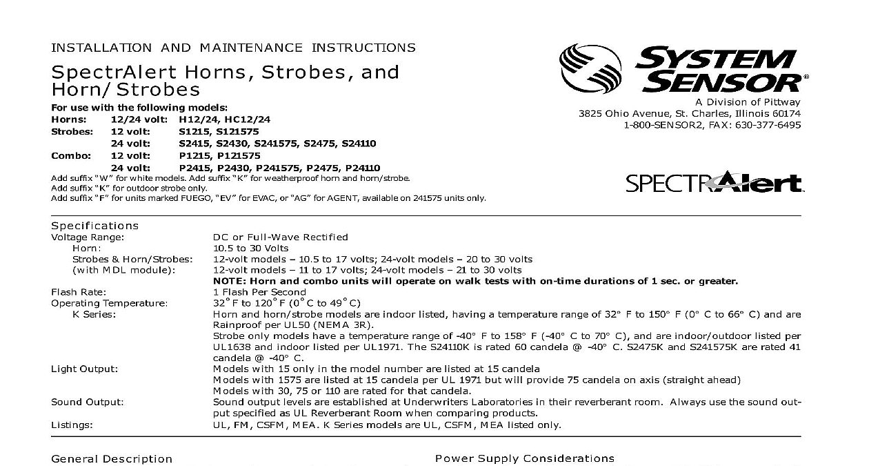
INSTALLATION AND MAINTENANCE INSTRUCTIONS Horns Strobes and use with the following models volt H12 24 HC12 24 volt volt volt volt S121575 S2430 S241575 S2475 S24110 P121575 P2430 P241575 P2475 P24110 SENSOR Division of Pittway 3825 Ohio Avenue St Charles Illinois 60174 FAX 630 377 6495 suffix for white models Add suffix for weatherproof horn and horn strobe suffix for outdoor strobe only suffix for units marked FUEGO for EVAC or for AGENT available on 241575 units only tert Range Horn Strobes MDL module Rate Temperature Series Output Output or Full Wave Rectified to 30 Volts models 10.5 to 17 volts 24 volt models 20 to 30 volts models 11 to 17 volts 24 volt models 21 to 30 volts Horn and combo units will operate on walk tests with on time durations of 1 sec or greater Flash Per Second F to 120 F 0 C to 49 C and horn strobe models are indoor listed having a temperature range of 32 cid 176 F to 150 cid 176 F 0 cid 176 C to 66 cid 176 C and are per UL50 NEMA 3R only models have a temperature range of 40 cid 176 F to 158 cid 176 F 40 cid 176 C to 70 cid 176 C and are indoor outdoor listed per and indoor listed per UL1971 The S24110K is rated 60 candela 40 cid 176 C S2475K and S241575K are rated 41 40 cid 176 C with 15 only in the model number are listed at 15 candela with 1575 are listed at 15 candela per UL 1971 but will provide 75 candela on axis straight ahead with 30 75 or 110 are rated for that candela output levels are established at Underwriters Laboratories in their reverberant room Always use the sound out specified as UL Reverberant Room when comparing products FM CSFM MEA K Series models are UL CSFM MEA listed only Description SpectrAlert series notification appliances are designed to meet the of most agencies governing these devices including ADA The National Fire Alarm Code UL FM CSFM MEA Also with your local Authority Having Jurisdiction for other codes or that may apply SpectrAlert series can be installed in systems using 12 or 24 volt having DC or full wave rectified FWR power supplies The can also be installed in systems requiring synchronization MDL required or systems that do not require synchronization module required This manual shall be left with the owner user of this equipment Alarm System Considerations and Non Temporal Coded Signals American National Standards Institute and the National Fire Alarm require that all horns used for building evacuation installed after July 1996 must produce Temporal Coded Signals other than those used for evacuation purposes do not have to pro the Temporal Coded Signal Temporal coding is accomplished by inter a steady sound in the following manner Sec Sec Sec Sec Sec Sec Supply Considerations typically supply DC filtered voltage or FWR full wave rectified The system design engineer must calculate the number of units in a zone based on the type of panel supply Be certain the sum of the device currents do not exceed the current capability of the panel are based on using the device current found in the subse charts and must be the current specified for the type of panel supply used Sizes designer must be sure that the last device on the circuit has sufficient to operate the device within its rated voltage When calculating voltage available to the last device it is necessary to consider the volt drop due to the resistance of the wire The thicker the wire the less voltage drop Generally for purposes of determining the wire size nec for the system it is best to consider all of the devices as the end of the supply circuit simulates case wire size resistance AWG solid AWG solid AWG solid AWG solid 8 ohms 1,000 ft 5 ohms 1,000 ft 3 ohms 1,000 ft 2 ohms 1,000 ft Assume you have 10 devices on a zone and each requires 50 average and 2000 Ft of 14 AWG wiring total length outgoing re The voltage at the end of the loop is 0.050 amps per device x 10 x 3 ohms 1,000 ft x 2000 ft 3 volts drop Manuals Online Only Only Hz Hz Hz CURRENT mA Models Models CURRENT mA Models Models RUSH CURRENT mA Models Models FWR DC FWR DC FWR 159 114 157 81 182 142 171 99 150 56 65 49 64 44 62 490 520 490 520 460 480 150 199 150 207 150 198 NA NA NA NA NA NA NA NA NA NA NA NA NA NA NA FWR DC FWR DC FWR 460 450 460 420 480 NA NA NA NA NA NA NA NA NA NA NA NA NA NA NA 201 183 219 183 216 440 340 460 330 480 560 450 570 420 620 78 145 170 123 159 102 141 220 140 191 115 174 FWR DC FWR DC FWR 204 135 208 135 185 FWR DC FWR DC FWR FWR DC FWR DC FWR 108 92 124 140 190 NA NA NA NA NA NA NA NA NA NA NA NA NA NA NA FWR DC FWR DC FWR 97 129 116 152 147 198 76 104 88 126 160 185 97 135 116 164 147 211 97 129 116 152 147 198 240 230 280 290 380 230 220 290 290 370 67 82 58 30 cd 15 cd 75 cd CURRENT mA Models FWR DC FWR DC FWR NA NA NA NA NA NA NA NA NA NA NA NA NA NA NA NA NA NA NA NA Models FWR DC FWR DC FWR CURRENT mA Models FWR DC FWR DC FWR 170 124 167 95 170 124 167 95 NA NA NA NA NA NA NA NA NA NA 172 125 168 97 173 125 168 95 NA NA NA NA NA NA NA NA NA NA Models FWR DC FWR DC FWR CURRENT mA Models FWR DC FWR DC FWR 193 152 181 113 164 193 152 181 113 164 NA NA NA NA NA NA NA NA NA NA 195 152 183 115 166 196 152 183 113 168 NA NA NA NA NA NA NA NA NA NA Models FWR DC FWR DC FWR 103 79 Hz Hz Hz CURRENT mA Models FWR DC FWR DC FWR 105 92 100 87 113 90 116 88 101 75 108 95 105 95 116 94 121 93 100 83 103 80 CURRENT mA Models FWR DC FWR DC FWR 191 148 167 131 167 188 146 169 132 169 182 136 162 119 156 182 137 162 119 157 196 151 172 139 174 192 150 175 137 177 184 140 164 123 160 188 139 163 124 162 CURRENT mA Models FWR DC FWR DC FWR 241 165 209 144 200 238 1