System Sensor spectralert-sp200- install and maint

File Preview
Click below to download for free
Click below to download for free
File Data
| Name | system-sensor-spectralert-sp200-install-and-maint-7835260914.pdf |
|---|---|
| Type | |
| Size | 652.63 KB |
| Downloads |
Text Preview
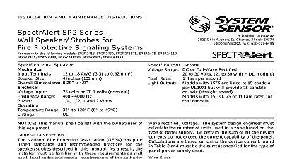
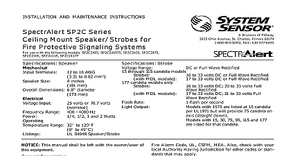
INSTALLATION AND MAINTENANCE INSTRUCTIONS SP200 Series Voltage Transformer Speakers Fire Protective Signaling Systems SENSOR Division of Pittway 3825 Ohio Avenue St Charles Illinois 60174 FAX 630 377 6495 Terminals Size Size Round Square Input Range Temperature Range to 18 AWG 3.31 to 0.82 mm2 inches 101 mm 187 mm 127 mm volts or 70.7 volts nominal 4000 Hz to 120 F 0 to 49 C 1 2 1 and 2 Watts S4048 This manual shall be left with the owner user of equipment Description National Fire Protection Association NFPA has pub standards and recommended practices for the speak described in this manual As a result the installer must familiar with these requirements as well as all local and special requirements of the authority having ju series speakers can be operated with distribution having an output voltage of either 25 volts or volts speakers operate at any one of four input power levels output sound level is selected at the time of installa but can be changed if necessary speaker is also equipped with a capacitive input to al for DC supervision wiring must be installed in compliance with the Na Electrical Code NEC and applicable local codes as as special requirements of the authority having juris using the proper wire size This also includes all NFPA Standards ANSI UL 1480 and NEC 760 Connect the speaker as shown in Figure 1 Do NOT loop electrical wiring under terminal Wires connecting the device to the control must be broken at the device terminal con in order to maintain electrical supervision 1 Electrical connections FROM NEXT OR EOL See Figure 2 as an example of how to select a 1 4 Watt when a 25 volt amplifier is being used Notice that header SW1 has two shunts One shunt is used to either 25 or 70.7 volts input The other shunt is to select input power of 1 4 1 2 1 or 2 Watts 2 ol ol Manuals Online 1 Sound levels for each transformer power tap 10 ft W W I Jl j W 1 4 W 75 Figure 3 The speaker can be flush mounted on a 4 X X 2 1 8 back box as follows Select the appropriate pair of diagonally opposite holes in the speaker grille Use the two 8 32 X 1 3 4 screws provided to attach the to the back box 10 ft W W J I JI 78 W 1 4 W 3 levels exceeding 130 rated signal voltage can the speaker Consequently an incorrect tap may cause speaker damage This means that a 25V tap is selected when a 70.7V amplifier is being speaker damage may result Therefore be sure to the proper taps for the amplifier voltage input level combination being used screws are included for attaching the speaker to the junction box If surface mounting is required an extension ring be necessary to give proper depth for mounting the The minimum depth required in the backbox ex ring combination is 2 5 8 Any combination of 4 4 backbox and 4 x 4 extension ring that gives an inte depth of at least 2 5 8 may be used SP201 SERIES SP200 SERIES Limitations of Speaker Strobes either of the voltage select or power select shunts is not plugged into of the appropriate option positions the speaker will not sound and will be no trouble indication at the panel Always make sure that the speakers are tested after installation per NFPA regulations speaker may not be heard The loudness of the speaker meets or the current Underwriters Laboratories standards However the may not attract the attention of a sound sleeper or one who has used drugs or has been drinking alcoholic beverages The speaker not be heard if it is placed on a different floor from the person in haz or if placed too far away to be heard over the ambient noise Traffic air machinery or music appliances may prevent even alert per from hearing the alarm The speaker may not be heard by persons are hearing impaired Limited Warranty Sensor warrants its enclosed speaker to be free from defects in ma and workmanship under normal use and service for a period of years from date of manufacture System Sensor makes no other ex warranty for this speaker No agent representative dealer or em of the Company has the authority to increase or alter the or limitations of this Warranty The Company obligation of Warranty shall be limited to the repair or replacement of any part of speaker which is found to be defective in materials or workmanship normal use and service during the three year period commencing the date of manufacture After phoning System Sensor toll free 800 SENSOR2 736 7672 for a Return Authorization number defective units postage prepaid to System Sensor Repair Depart RA 3825 Ohio Avenue St Charles IL 60174 Please a note describing the malfunction and suspected cause of failure Company shall not be obligated to repair or replace units which are to be defective because of damage unreasonable use modifica or alterations occurring after the date of manufacture In no case the Company be liable for any consequential or incidental damages breach of this or any other Warranty expressed or implied whatsoever if the loss or damage is caused by the Company negligence or fault states do not allow the exclusion or limitation of incidental or conse damages so the above limitation or exclusion may not apply to This Warranty gives you specific legal rights and you may also have rights which vary from state to state Manuals Online Sensor 2000