System Sensor SYNC-1 Manual

File Preview
Click below to download for free
Click below to download for free
File Data
| Name | system-sensor-sync-1-manual-4863297051.pdf |
|---|---|
| Type | |
| Size | 1.11 MB |
| Downloads |
Text Preview
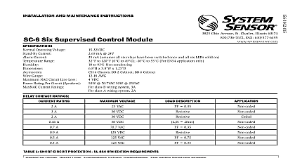
INSTALLATION AND MAINTENANCE INSTRUCTIONS Accessory Card Ohio Avenue St Charles Illinois 60174 FAX 630 377 6495 Devices Appliances H12 24 H12 24K HC12 24 S12XX S24XX SC24XX P12XX PC24XX SP2C24XX SP2424XX SP2W24XX DS2475XXX S1224MC S1224MCW SP2W1224MC P1224MC Series P1224MCW S1224MC Series CH24MC SP3R1224MC SP3R1224MCW SP2R1224MCK P2RX P2WX P4RX P4WX SWX SCRX SCWX HRX HWX CHX CHRX CHWX CHSRX CHSWX PC2RX PC4RX PC4WX H12 24X PA400X S1224MCX SC24XX SP2R1224MCX CH24MCX MHR A MHW A MHRZA MHWZA SPSX SPSCX B200SR suffix for white models Modules Used with a UL listed Six Supervised Control Module Panels Refer to six supervised control module installation manual for list Supplies Use any regulated power supply that is UL 1481 listed Any UL 864 listed power supply may also be used but it must be intended for use with NAC devices to 120 0 to 49 AWG shunts 4 screws 2 standoffs Current 0 position 2 or 4 position if connected to supply 2.5mA Temperature Gauge Loop Power Supply Current Rating Class A Style Z Class B Style Y Supply Voltage Range Load on a Loop Class A Style Z Class B Style Y maximum alarm current maximum load on a loop both cases 1 Refer to installation manual to determine the number of compatible notification appliances their voltage requirements current requirements and wire size The sum the inrush currents of all the notification appliances connected to a loop must be equal or less than the Loop Power Supply Current Rating See NOTE 1 per pair See NOTE 1 to compatible power supply installation manual NOTE 1 NOTE 1 DESCRIPTION SYNC 1 Accessory Card is designed to operate with the Six Supervised Module It works with the SpectrAlert series of horns strobes and to provide a means of synchronizing the temporal coded horns the one second flash timing of the strobe and silencing the of the horn strobe combination over a two wire circuit while leaving strobes active Each SYNC 1 Accessory Card consists of three electrically synchronization circuits Although they are isolated from each other three circuits are synchronized with respect to each other A SYNC 1 Ac Card enables a Six Supervised Control Module to synchronize a maxi of three Class A or six Class B notification appliance circuits NACs This manual should be left with the owner user of this equipment CODING ON MA12 24D AND PA400 HORNS Program module to provide temporal coding by inserting jumper on on the SYNC 1 board Do this prior to installing the SYNC 1 Accessory onto the Six Supervised Control Module Connect only sounders producing a continuous tone to the module NAC are incapable of operation on a temporal tone Notification Appliance Circuit 1 INSTALLATION OF SYNC 1 Supervised Module OF SYNC 1 ACCESSORY CARD two screws into the holes on the bottom center of the Six Supervised Module On the front side of the board install two standoffs onto screws The SYNC 1 Accessory Card plugs into the pins of the Six Super Control Module The pins on the module are labeled GENERA Remove the three large shunts on the Sync Generator pins Line up the on the accessory card with the pins on Six Supervised Control Module Ensure the pins and holes are lined up correctly or the SYNC 1 card will not operate properly Push down firmly on the accessory Install two screws into standoffs to secure the board used with the SYNC 1 Accessory Card the Six Supervised Control Mod can accommodate a maximum of three power supplies limited to a maxi of 3 Amp each The SYNC 1 Accessory Card control circuitry can only energized by connecting power supplies to the terminals at the even 0 2 4 of the Six Supervised Control Module All power connections must be made at even positions The master control of SYNC 1 Accessory Card is powered by the supply connected to the at position 0 Therefore there must be a supply connected to for the SYNC 1 Accessory Card to be operational SYNC 1 Accessory Card used with a Six Supervised Control Module is to a maximum of three power supplies therefore each circuit pair 2 3 4 5 must share a supply in order for all NACs to powered Due to supply sharing the maximum load on a Class A NAC is to 3A while the maximum load on a pair of Class B NACs is limited 3A total Power Supply Monitoring must be disabled on the Control Module using the SYNC 1 Accessory Card on the Six Supervised Control Module to the Six Supervised Control Module installation manual for more detail its configuration and wiring requirements interconnect SYNC 1 Accessory Cards wire the Slave and Horn connections shown in Figure 2 The slave wires will synchronize all NACs correspond to the interconnected boards Any SYNC 1 which has no connections to its in terminals will operate as a master It will generate a signal which will duplicated by all interconnected units downstream The horn wires will horn control on all NACs corresponding to the interconnected boards control also requires a silenceable NAC circuits to be wired to the horn terminals of the master SYNC 1 Accessory Card as shown in Figure 3 maximum of 11 Slaves Sync 1 Cards can be connected to a Master Sync 1 totalling 12 horn and slave wiring interconnecting SYNC 1 accessory cards must be con within the same enclosure If multiple enclosures are used they must be lo in the same room within 20 feet of each other with all horn and slave wiring enclosures routed inside of conduit This conduit should be grounded metal no other field wiring 2 CONNECTING TWO SYNC 1 CARDS CLASS B OPERATION ONE POWER SUPPLY USED NAC PS NAC PS POWER SUPPLY MONITOR POWER SUPPLY MONITOR SHORT CIRCUIT PROTECTION is Limited POWER SUPPLY MONITOR POWER SUPPLY MONITOR SHORT CIRCUIT PROTECTION 3 HORN OPERATION is Limited NAC Output Next SYNC 1 Horn In LIM