System Sensor WFD Explosion Proof Manual

File Preview
Click below to download for free
Click below to download for free
File Data
| Name | system-sensor-wfd-explosion-proof-manual-1587230964.pdf |
|---|---|
| Type | |
| Size | 1.12 MB |
| Downloads |
Text Preview
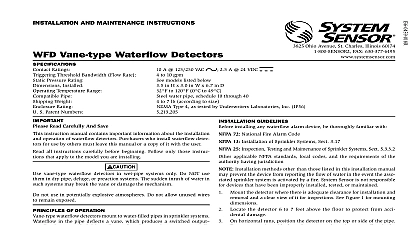
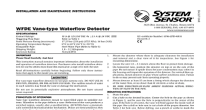
I and mainTenance insTrUcTions explosion Proof Waterflow detectors 3825 Ohio Avenue St Charles Illinois 60174 FAX 630 377 6495 Ratings Threshold Bandwidth Flow Rate Pressure Rating Installed Temperature Range Pipe Weight Rating Hazardous Atmosphere Classification Patent Number Read Carefully And Save 2.5 A 24 VDC A 125 250 VAC to 10 gpm models listed below in H 8.8 in W 7.0 in D to 120 0 to 49 water pipe schedule 10 or 40 to size 4 indoor outdoor use I Groups B C D Div 1 Class II Groups E F G Div 1 Class III Div 1 instruction manual contains important information about the installation operation of waterflow detectors Purchasers who install waterflow detec for use by others must leave this manual or a copy of it with the user all instructions carefully before beginning Follow only those instruc that apply to the model you are installing vane type waterflow detectors in wet pipe systems only Do NOT use in dry pipe deluge or preaction systems The sudden inrush of water in systems may break the vane or damage the mechanism of oPeraTion waterflow detectors mount to water filled pipes in sprinkler systems in the pipe deflects a vane which produces a switched output after a specified delay All waterflow detectors have a pneumatically mechanical delay mechanism Delays do NOT accumulate they re if the flow of water stops before the entire delay has elapsed All switches when the water flow rate is 10 gallons per minute or greater but will actuate if the flow rate is less than 4 gallons per minute This System Sen installation manual covers the following waterflow detectors for sprinkler alarm applications Size Pressure psig thru 40 thru 40 thru 40 thru 40 thru 40 thru 40 thru 40 thru 40 Pressure Rating 400 psig as approved by Factory Mutual Research NOT use any of the WFD models on copper pipe The clamping forces of mounting bolts may collapse the pipe sufficiently to prevent the detector functioning properly NOT install steel or iron pipe sections in copper piping for mounting a detector Incompatibility between the dissimilar metals causes bi corrosion Not for use in potable water systems systems where sand or other is present or systems employing other than water GUideLines installing any waterflow alarm device be thoroughly familiar with 72 National Fire Alarm Code 13 25 of Sprinkler Systems Section 3.17 Inspection Testing and Maintenance of Sprinkler Systems Section applicable NFPA standards local codes and the requirements of the having jurisdiction Installation methods other than those listed in this installation manual prevent the device from reporting the flow of water in the event the asso sprinkler system is activated by a fire System Sensor is not responsible devices that have been improperly installed tested or maintained Mount the detector where there is adequate clearance for installation and and a clear view of it for inspections See Figure 1 for mounting to protect from damage 6 to 7 feet above the floor On horizontal runs position the detector on the top or side of the pipe not mount it upside down because condensation may collect in the and impair the operation of the detector For vertical flow appli mount the detector on pipe through which water flows upward the unit may not operate properly Mount the detector at least 6 inches from a fitting that changes the direc of water flow and no less than 24 inches from a valve or drain Be sure the direction of flow arrow matches the direction of flow in the pipe the appropriate personnel regarding the proper tools and procedures installing this device in a area Disconnect supply cir before opening the cover to reduce the chances of ignition of hazardous Secure the cover and cover screws prior to activating circuits cover screws to 40 in lbs min insTrUcTions Drain the pipe Cut a hole at the desired location Center the hole in the pipe as shown Figure 2 and be sure the hole is perpendicular to the center of the Before drilling use a punch or scribe to mark the drill site to pre the bit from slipping If the hole is off center the vane will bind the inside wall of the pipe Use a drill or hole saw to cut a hole of proper diameter See Table 1 for hole size drilling the hole with a hole saw make certain that the center of the cut not remain in the pipe Remove burrs and sharp edges from the hole Clean and remove all scale foreign matter from the inside of the pipe for one diameter on each of the hole to ensure free movement of the vane Clean the outside the pipe to remove dirt metal chips and cutting lubricant Seat the O ring or gasket against the saddle and mount the detector di to the pipe Carefully roll the vane opposite the direction of flow insert it through the hole Seat the saddle firmly against the pipe so the locating boss goes into the hole Install the U bolt tightening the nuts alternately to ensure a uniform See Table 1 for torque values Remove the metal cover with the tamper proof wrench provided Manu actuate the limit to check for binding If the vane binds remove the and correct the cause before proceeding sure the direction of flow arrow points in the right direction or else water will go unreported See Figure 3 1 moUnTinG dimensions TesTinG Fill the sprinkler system and check for leaks around the waterflow detec If it leaks first check for the proper torque on the U bolt nuts If the persists drain the system and remove the detector refer to Mainte Check for dirt or foreign objects under the gasket and make sure the pipe surface is not dented Reinstall the detector and check again leaks Do not proceed until all leaks have been stopped Connect an ohmmeter or continuity tester across the COM and B NO terminals The ohmmeter should indicate an open circuit Deflect the actuator lever and hold it until the pneumatic delay shaft the switch buttons The ohmmeter or continuity tester should a short circuit after the delay has elapsed If there is no delay the setting of the delay adjustment dial 3 assembLY diaGram 2 moUnTinG hoLe LocaTion 6.5 P N SADDLE VANE PADDLE VANE OF FLOW WHILE INSERTING SIZE TO TABLE 1 BLOCK P N A77 01 02 NUT OF ARROW All models have two SPDT switches Switch contacts COM and B NO closed when water is flowing and open when it is not Connect the as shown in Figure 4 depending on the application When connected to a listed sprinkler fire alarm control panel the initiat circuit must be non silenceable A ground screw is provided with all waterflow detectors When ground is required clamp wire with screw in hole located between conduit holes See Figure 3 If a second conduit entry is required remove the plug using a hex wrench BURRS FROM EDGE OF HOLE CLEAN OUT SCALE FOREIGN MATTER FROM INSIDE WALL OF PIPE 1 Model Size in 25 35 40 50 60 80 ft lb ft lb Voltage Electrocution Hazard Do not handle live AC wiring or work on a to which AC power is applied Doing so may result in injury or death utilizing switches at voltages greater than 74VDC to provide all disconnection must be incorporated in the fixed such as a circuit breaker or 49VAC 4 Wfd WirinG remove a detector LISTED PANEL