System Sensor WFD FACP Wiring and Typical Bell Connection

File Preview
Click below to download for free
Click below to download for free
File Data
| Name | system-sensor-wfd-facp-wiring-and-typical-bell-connection-2379841605.pdf |
|---|---|
| Type | |
| Size | 661.22 KB |
| Downloads |
Text Preview
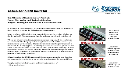
02 06 All System Sensor Users Systems Applications Engineers Technical Support TECHNICAL FIELD BULLETIN WFD FACP wiring and typical bell connection Sensor Technical Support would like to address a common question regarding how to wire the waterflow switch in an alarm circuit WFD has two Form C switches Both switches have a common terminal marked COM for a point an A terminal which is normally closed and a B terminal which is normally open stay in this state when the switch is not in alarm Both switches are isolated and protected from voltages see drawings for 24vdc and 120vac first switch can be used by the fire alarm control panel FACP initiating loop which monitors for alarm condition In this case the switch initiated by the flow of water changes state and places a across the end of line resistor which is used for supervision The FACP recognizes this as an water is flowing initiating the FACP to register an alarm condition the second switch closes the positive 24vdc or 120vac to complete its path to the bell When the switch closes and the registers the alarm the bell will sound System Sensor does not approve inspect or certify installations The Authority Having Jurisdiction may to the listings or labeling practices of an organization that has evaluated the product and stands in a position to compliance with appropriate standards for the installation of listed items Ohio Avenue St Charles Illinois 60174 Phone 800 SENSOR2 Fax 630 377 6583 http www systemsensor com