System Sensor wfd-installation

File Preview
Click below to download for free
Click below to download for free
File Data
| Name | system-sensor-wfd-installation-4615789320.pdf |
|---|---|
| Type | |
| Size | 676.10 KB |
| Downloads |
Text Preview
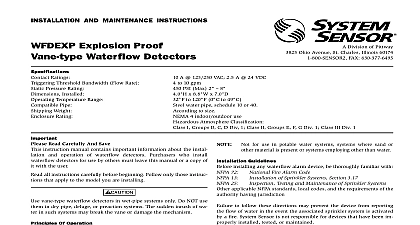
SYSTEM SENSOR Division of Pittway 3825 Ohio Avenue St Charles Illinois 60174 FAX 630 377 6495 AND MAINTENANCE INSTRUCTIONS Vane type Waterflow Ratings Threshold Bandwidth Flow Rate Pressure Rating Installed Temperature Range Pipe Weight Rating A 125 250 VAC 2.5 A 24 VDC to 10 gpm PSI Max 2 8 as tested by Underwriters Laboratories U L PSI Max 2 8 as tested by Factory Mutual x 3.0 W x 6.7 D to 120 F 0 to 49 C water pipe schedule 10 or 40 to 7 lb according to size Type 4 as tested by Underwriters Laboratories Inc Read Carefully And Save instruction manual contains important information about the instal and operation of waterflow detectors Purchasers who install detectors for use by others must leave this manual or a copy of with the user all instructions carefully before beginning Follow only those instruc that apply to the model you are installing vane type waterflow detectors in wet pipe systems only Do NOT use in dry pipe deluge or preaction systems The sudden inrush of wa in such systems may break the vane or damage the mechanism not use in potentially explosive atmospheres Do not allow unused to remain exposed Of Operation waterflow detectors mount to water filled pipes in sprinkler sys Waterflow in the pipe deflects a vane which produces a switched after a specified delay All waterflow detectors have a controlled mechanical delay mechanism Delays do NOT they reset if the flow of water stops before the entire delay elapsed All switches actuate when the water flow rate is 10 gallons minute or greater but will not actuate if the flow rate is less than 4 per minute This System Sensor installation manual covers the fol waterflow detectors for sprinkler fire alarm applications Waterflow detector Schedule 10 40 2 Waterflow detector Schedule 10 40 2 1 2 Waterflow detector Schedule 10 40 3 Waterflow detector Schedule 10 40 3 U L Listed only Waterflow detector Schedule 10 40 3 1 2 Waterflow detector Schedule 10 40 4 Waterflow detector Schedule 10 40 5 Waterflow detector Schedule 10 40 6 Waterflow detector Schedule 10 40 8 NOT use any of the WFD models on copper pipe The clamping forces the mounting bolts may collapse the pipe sufficiently to prevent the de from functioning properly NOT install steel or iron pipe sections in copper piping for mounting a detector Incompatibility between the dissimilar metals causes corrosion Guidelines installing any waterflow alarm device be thoroughly familiar with 72 13 25 applicable NFPA standards local codes and the requirements of the having jurisdiction Fire Alarm Code of Sprinkler Systems Section 3.17 Testing and Maintenance of Sprinkler Systems to follow these directions may prevent the device from reporting flow of water in the event the associated sprinkler system is activated a fire System Sensor is not responsible for devices that have been im installed tested or maintained Mount the detector where there is adequate clearance for installation removal and a clear view of it for inspections See Figure 1 for dimensions Locate to protect from damage 6 to 7 feet above the floor On horizontal runs position the detector on the top or side of the pipe not mount it upside down because condensation may collect in the and impair the operation of the detector For vertical flow ap mount the detector on pipe through which water flows up Otherwise the unit may not operate properly Mount the detector at least 6 inches from a fitting that changes the di of water flow and no less than 24 inches from a valve or drain Be sure the direction of flow arrow matches the direction of flow the pipe Instructions Drain the pipe Cut a hole at the desired location Center the hole in the pipe as in Figure 2 and be sure the hole is perpendicular to the center the pipe Before drilling use a punch or scribe to mark the drill site prevent the bit from slipping If the hole is off center the vane will against the inside wall of the pipe Use a drill or hole saw to cut a of the proper diameter See Table 1 for hole size drilling the hole with a hole saw make certain that the center of the does not remain in the pipe Remove burrs and sharp edges from the hole Clean and remove scale and foreign matter from the inside of the pipe for one di on each side of the hole to ensure free movement of the Clean the outside of the pipe to remove dirt metal chips cutting lubricant Seat the O ring or gasket against the saddle and mount the detector di to the pipe Carefully roll the vane opposite the direction of flow insert it through the hole Seat the saddle firmly against the pipe Manuals Online that the locating boss goes into the hole the U bolt tightening the nuts alternately to ensure a uniform See Table 2 for torque values Remove the metal cover with the tamper proof wrench provided Move actuator lever back and forth to check for binding If the vane remove the detector and correct the cause before proceeding sure the direction of flow arrow points in the right direction or else flow will go unreported See Figure 3 Testing Fill the sprinkler system and check for leaks around the waterflow If it leaks first check for the proper torque on the U bolt If the leak persists drain the system and remove the detector to Maintenance Check for dirt or foreign objects under the and make sure that the pipe surface is not dented Rein the detector and check again for leaks Do not proceed until leaks have been stopped Connect an ohmmeter or continuity tester across the COM and B terminals The ohmmeter should indicate an open circuit Deflect the actuator lever and hold it until the pneumatic delay shaft the switch buttons The ohmmeter or continuity tester should a short circuit after the delay has elapsed If there is no delay the setting of the delay adjustment dial Voltage Electrocution Hazard Do not handle live AC wiring or work on a to which AC power is applied Doing so may result in injury or death All models have two SPDT switches Switch contacts COM and B are when water is flowing and open when it is not Connect the as shown in Figure 4 depending on the application When connected to a listed sprinkler fire alarm control panel the initi circuit must be nonsilenceable A ground screw is provided with all waterflow detectors When is required clamp wire with screw in hole located between entrance holes See Figure 5A page 4 a second conduit entry is required remove the knockout plug using flat blade screwdriver as shown on Figure 5B page 4 Strike sharply a hammer to pierce the wall of the knockout plug Move to an wall section and repeat until the plug falls out Make sure that waterflow detector is supported adequately during this operation avoid injury 1 Mounting dimensions diameter 5 1 4 nut saddle vane width pipe diameter 3 2 Mounting hole location burrs from edge of hole Clean out scale and foreign for one pipe diameter on each side of hole Delay Adjustment pneumatic delay is preset at the factory to dial setting 2 To adjust the turn the adjustment dial clockwise to increase the delay counter to decrease it The delay is adjustable from 0 to 70 seconds See 6 page 4 the delay to the minimum required to prevent false alarms flow surges extended service parts of the detector may become worn reducing delay time and causing false alarms If this happens increase the de If the delay is already at the maximum replace the mechanical delay Refer to Maintenance for ordering replacement parts 1 2 MODEL 25 30 35 40 50 60 80 MODEL 25 30 35 40 50 60 80 SIZE I ft lb ft lb model listing on page 1 for pipe sizes Manuals Online 3 Assembly diagram proof wrench WFDW L