Valcom 40 Watt Explosion Proof Horn

File Preview
Click below to download for free
Click below to download for free
File Data
| Name | valcom-40-watt-explosion-proof-horn-5210673948.pdf |
|---|---|
| Type | |
| Size | 624.12 KB |
| Downloads |
Text Preview
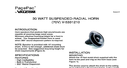
PagePac 1 WATT EXPLOSION PROOF HORN Proof Horn Speakers are constructed that all electrical components are sealed from atmosphere and may be used in areas where substances are present The explosion speakers require some assembly before see Figure 1 proof speakers are mounted using the mounting bracket attached to each These brackets are intended primarily mounting on flat surfaces and each bracket three holes which may be used for installing hardware Speaker position in the verti axis may be adjusted by loosening the bolts secure the bracket to the speaker body Figure 1 UL CSA Approved Heavy Duty Construction Omni Directional Mounting Bracket 5 Tap Settings 2.5W 5W 10W 20W 40W Specifications Dispersion Wide Angle Input 70.7V Line Output 101dB 113dB 16.5 x 21.5 x 54.6cm 27 lbs 12.2 kg Temperature 4 to 131 F 20 to 55 C Humidity to 95 the horn and the base of the speaker by the base of the speaker tightly and turning horn counterclockwise see Figure 1 View 1 the two halves of the speaker base by the eight bolts see Figure 1 View 2 the conduit entry into the speaker as by local ordinances for the class and type speaker used see Figure 1 View 3 the speaker cable separate the inner wires for distance of 3 or 4 inches by stripping away insu from the main cable If using shielded cable inner wire without insulation is the shield wire approximately 1 2 inch of insulation from the of each of the smaller insulated wires The cable must enter the speaker through a that has been installed according to local for the class and type of speaker the wires on terminals 1 and 2 If cable is used either splice the shield to provide a continuous shield to the next or clip the shield wire at the point where emerges from the main cable as appropriate shield wire should not be terminated on the Manuals Online Manuals Online ASSISTANCE calling have a VOM and a telephone test available and call from the job site Call 540 and ask for PagePac Technical Sup or call 540 427 6000 for Valcom 24 hour Support Visit our websites at and www valcom com repairs be necessary attach a tag to the clearly stating company name address number contact person and the nature of problem Send the unit to Inc Repair Dept Hollins Road VA 24019 5056 ADJUSTMENTS necessary remove the power tap selection wire wire and reattach it to the desired power The numbers on the terminal strip indicate the in watts for a 70 volt paging system on a paging system the output will be approxi 1 8 of that indicated see Table 1 the two halves of the speaker case reinstalling the eight bolts TO AMPLIFIER special care in removing back cover of proof driver enclosure Part 1 to avoid machined surfaces Prior to reassem make certain that joining surfaces of enclo are free of dirt Tighten all cover bolts To provide the specified protection in locations please note that no com of any type is to be applied on machined 1 40 Watt Explosion Proof 70V Power 25V Power Setting Ohms Watts Watts TO DESIRED POWER TAP explosion proof speaker has a one conduit access into the sealed Conduit entry into the speaker must made in accordance with local codes the Class and Group of speaker being See Connection Procedures AMPLIFIER 1 Manuals Online Manuals Online