Valcom Multi-Zone Microphone

File Preview
Click below to download for free
Click below to download for free
File Data
| Name | valcom-multi-zone-microphone-2846905137.pdf |
|---|---|
| Type | |
| Size | 643.72 KB |
| Downloads |
Text Preview
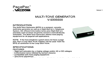
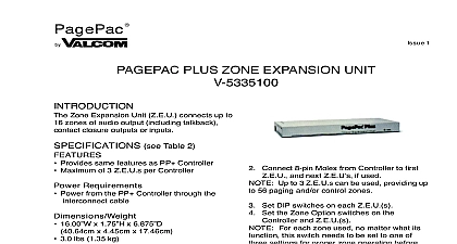
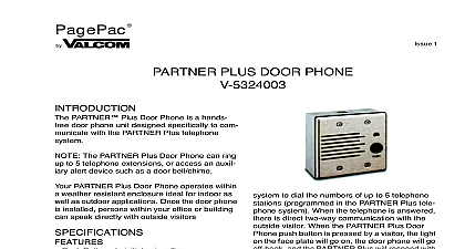
PagePac 1 MICROPHONE high fidelity desk microphone provides high low noise single and multi zone paging to existing paging products A cardioid element suppresses background noise is housed on the end of a flexible tube You page through a momentary push button for pages or make a long page with a lock on Front panel LEDs indicate paging status Figure 1 back panel is shown in Figure 2 An attached socket transformer provides power to the unit for tip and ring busy buss and dry closure are made at a compression screw block You can adjust the output volume by screwdriver The multi zone model has a for selecting dedicated single zone paging DTMF Pad for Multi Zone Access Can be Switched to Dedicated Single Zone Momentary Push or Lock On Page Button Front Panel LEDs Requirements 120 VAC 60 Hz Base 7 x 3 x 5 x 7.62cm x 12.7cm 14 35.56cm 2.50 lbs 1.13 kg make a short page press and hold the larger contact push button To make a longer press the smaller locking push button when page is over press this push button again to On the multi zone model use the pad to select zone addresses or implement features Refer to your Page Controller for zone options three LEDs on the front panel show paging A flashing yellow LED indicates a long page The red LED indicates a busy condi on the system The green LED indicates that microphone is on and ready to initiate a page when the unit is paging volume can be adjusted by using the screw output level at the back panel Figure 2 microphone has rubber feet for placing on a desktop Connect the transformer to standard 120 VAC 60 Hz wall socket Figure 3 the wiring connections at the microphone block Multiple microphones may be to an amplifier in either a star or daisy chain as shown in Figure 4 Choose the that minimizes the length of wiring 5 shows the wiring diagram for connecting to a PagePac D Series AmpliCenter An additional terminal block is recom with the star configuration for connecting various incoming wires at the amplifier end Manuals Online Manuals Online The shielding for the wires should NOT be to the GND screw at any microphone the star configuration The Shield should remain continuous to the of the wire run and should only be grounded the amplifier 6 shows the wiring diagram for connecting to a Paging Controller Unit ASSISTANCE calling have a VOM and a telephone test available and call from the job site Call 540 and ask for PagePac Technical Sup or call 540 427 6000 for Valcom 24 hour Support or visit our websites at and www valcom com repairs be necessary attach a tag to the clearly stating company name address number contact person and the nature of problem Send the unit to Inc Repair Dept Hollins Road VA 24019 5056 ELECTRET ELEMENT HIGH SUPPRESSION BACKGROUND NOISE INDICATORS PAD FOR ACESS PUSHBUTTON SHORT PAGES PUSHBUTTON LONG PAGES 1 Multi Zone Microphone Features Manuals Online Manuals Online CONTROL FOR DEDICATED PAGING Zone No 22700 003 Inc VA 24019 5056 SCREW BLOCK CONNECTED TO WALL SOCKET PROVIDES 12 VAC 2 Back Panel Controls and Connectors Enlarged View D T PU T U S Y U S S ONT AC T LOSU R E 3 Wiring Connections on Microphone Terminal Block Manuals Online Manuals Online WIRING CHAIN WIRING WIRE SMALLER THAN AWG NO GREATER 1000 FT TOTAL LAST MICHROPHONE WIRE SMALLER THAN AWG UP TO 1000 FT 4 Star or Daisy Chain Wiring Configurations V OUT IN IN SERIES AMPLICENTER BLOCK V OUT IN IN BLOCK C BUSY BUSY 1 C BUSY BUSY 2 C BUSY BUSY 3 C BUSY BUSY 4 WIRING ALL OTHER MICROPHONES ARE ATTACHED C C BUSY A SIMILAR MANNER TO THE TERMINAL BLOCK CHAIN WIRING 5 Typical Connections to a D Series AmpliCenter STRIP 0dBu N B AA CHAIN WIRING TO FIGURE 5 FOR STAR WIRING C BUSY C BUSY 1 2 C BUSY 3 C BUSY 4 6 Typical Connections to Paging Controller Unit Manuals Online Manuals Online