Valcom PP+ Controller and Controller with Power Supply
File Preview
Click below to download for free
Click below to download for free
File Data
| Name | valcom-pp-controller-and-controller-with-power-supply-5614209783.pdf |
|---|---|
| Type | |
| Size | 1.39 MB |
| Downloads |
Text Preview
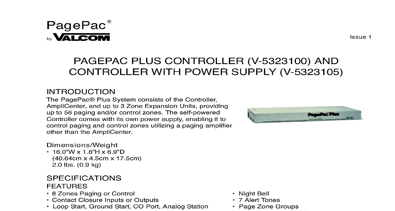
PagePac 1 PLUS CONTROLLER V 5323100 AND WITH POWER SUPPLY V 5323105 PagePac Plus System consists of the Controller and up to 3 Zone Expansion Units providing to 56 paging and or control zones The self powered comes with its own power supply enabling it to paging and control zones utilizing a paging amplifier than the AmpliCenter 16.0 x 1.8 x 6.9 x 4.5cm x 17.5cm lbs 0.9 kg 8 Zones Paging or Control Contact Closure Inputs or Outputs Loop Start Ground Start CO Port Analog Station Dry Loop Access Controller with Power Supply for Applications with Night Bell 7 Alert Tones Page Zone Groups Flexible Numbering Plan Amplified Speakers or Amplifiers other than PagePac Mount the PagePac Plus Controller and Zone Expansion Units if any to either a wall Figure 1 cabinet or a rack below the AmpliCenter or other amplifier see Figure 2 When installing the PagePac Plus Controller leave at least four inches of space above and below proper ventilation the paging equipment in a ventilated room where there is easy access to speaker cabling prefer in the telephone equipment room Manuals Online Manuals Online 1 Wall Mounted Hardware 2 Rack Mounted Hardware Connect background music input wires to Left and Right terminals if stereo or Left and Ground if not Figure 3 The optional audio source can be a CD or tape player AM FM or commercial radio or other device Manuals Online Manuals Online more than one AmpliCenter is used in the paging system each one can be connected to the same source or different audio device if desired 3 Music Input Connections on AmpliCenter Plug modular cord into connectors Amp on Controller and In on AmpliCenter Figure 4 If an amplifier other than the AmpliCenter is used refer to page 10 There you will find wiring dia and notes 4 Page In Connection from Controller to AmpliCenter Connect 8 pin Molex connector from AmpliCenter to Controller see Figure 5 Connectors can only go in one way DO NOT force in you are using another type of amplifier refer to the example system setups Manuals Online Manuals Online 5 8 pin Molex Connector from AmpliCenter to Controller to Controller will occur if the Molex connector from AmpliCenter is into the right connector This goes to Zone Expansion Units Set the AmpliCenter Telephone Mode Selection Switch to Dry Loop 600 Ohms Far left setting Figure 6 6 AmpliCenter Mode Switch Setting Connect 8 pin Molex from Controller to Zone Expansion Unit s if used See Figure 7 Up to 3 Zone Expansion Units can be used providing up to 56 paging and or control zones 7 8 pin Molex Connector from Controller to Zone Expansion Unit s Manuals Online Manuals Online Set DIP switches on each Zone Expansion Unit if any See Figure 8 These DIP switches must be set correctly in order for the Controller to recognize the additional 8 Setting Zone Expansion Unit DIP Switches Using a small standard screwdriver make the following adjustments Adjust the Low Frequency Cut Off control to center position This control cuts out the low fre bass so that horns and small speakers are not over driven and distorted by excessive energy Cut off frequency is continuously adjustable from 50Hz full CCW rotation to 400 Hz CW rotation See Figure 9 Adjust the Page VOX voice activated sensitivity to the fully counterclockwise position Adjust Music Input level to the center position Clockwise rotation will increase the level Listen set to a comfortable level Adjust Music Ducking level to the fully counterclockwise position This feature allows music to to be heard during a page but at a reduced level The range is less than dB full to dB full CW If music is not connected set to full CCW 9 Sound Level Adjustments on AmpliCenter Manuals Online Manuals Online Set Telephone Mode switch on Controller to match host telephone system interface port type Figure 10 10 Setting Controller Telephone Mode Switch Connect cable from host telephone system to Controller Page Input Figure 11 Depending on the type of host telephone system interface port the connection may differ slightly the illustration to the right A direct 4 conductor cord from the Controller to the telephone system also be used bypassing the connector block GREEN WIRE TO SYSTEM TIP T RED WIRE TO SYSTEM RING R BLACK WIRE TO THE PAIRED DRY CONTACT CONTROL LEAD GROUND YELLOW WIRE TO THE PAIRED DRY CONTACT CONTROL LEAD C1 11 Connecting Host Telephone System to Controller Connect two wires from the night bell analog station port on the host telephone system to Controller bell N B input See Figure 12 12 Night Bell Connection to Controller Manuals Online Manuals Online Set the Zone Option switches on the Controller and Zone Expansion Units if any For each zone used no matter what its function this switch needs to be set to one of three set for proper zone operation Controller has eight switches for zones 1 8 Each subsequent Zone Expansion Unit has switches for 9 24 25 40 and 41 56 13 Setting Zone Option Switches on Controller and Zone Expansion Units SPEAKERS each speaker to the appropriate Home Run or Speaker to speaker wiring scheme as shown on floor plan See Figure 14 14 Speaker Wiring Methods Manuals Online Manuals Online 15 Contact Closure Zone Wiring to Controller Test speaker wiring for short circuits the resistance of each home run wiring with an ohmmeter Any pair indicating a value of less 15 Ohms must be rechecked for possible shorted wiring or speakers Correct any problems and Make zone connections to Controller and any Zone Expansion Units See Figure 15 zone connectors on the Controller and Zone Expansion Units can accommodate up to two 22 AWG or four 24 AWG wires per zone output DO NOT over tighten zone connector screws zone option switch setting with Zone Map and Zone Configuration Tables as you connect each A 70V audio output setting going to other than speakers may damage other equipment Manuals Online Manuals Online UP SYSTEM all zones wired and connected to the Controller and Zone Expansion Units if any initial testing begin Refer to Controls and Indicators Terminals and Connector Once initial testing is done you begin to program the Controller with the features for each zone Plug the power cord into the AC input connector on the AmpliCenter The following should happen The green Power LED on the AmpliCenter will turn on and stay on The green Page Access LED on the AmpliCenter also turns on but will go out after a few On the Controller verify that the green Phone System Enabled LED if off and that the yellow If background music is connected adjust the Music In Input Level control on the AmpliCenter s Access Enabled LED is off an acceptable level If an amplifier other than the AmpliCenter is used make sure it is powered up and verify the LEDs Make an All Zone test page Readjust sound levels by adjusting speaker tap settings if required Readjust Music Input level to the desired loudness relative to paging loudness Some loudspeaker taps may have to be re adjusted to get even coverage at all locations Be sure the final speaker tap setting totals do not exceed the power rating of the AmpliCenter Begin programming the Controller refer to Programming Section CONTROLLER CONNECTIONS wiring diagrams in Figures 16 through 18 illustrate the connection of the Self Powered Controller other amplifiers In this way most features associated with the Controller can be utilized with ampli other than the AmpliCenter Refer to Tables 1 and 2 for gain and sensitivity settings TO GENERIC AMPLIFIER install the Controller to a Generic Amplifier see Figure 16 Connect 0dBu or 0dBm output to amplifier audio input Refer to Tables 1 and 2 for proper audio input requirements and volume control settings Connect Amplifier Audio Output 70.7V to Amplified Audio Input on Controller Adjust Controller volume c