Valcom Universal Voice Coil and 70V Door Speaker

File Preview
Click below to download for free
Click below to download for free
File Data
| Name | valcom-universal-voice-coil-and-70v-door-speaker-4270816935.pdf |
|---|---|
| Type | |
| Size | 659.76 KB |
| Downloads |
Text Preview
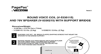
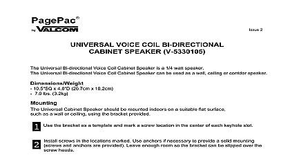
PagePac 2 Voice Coil and Volt Door Speaker V 5330230 Manual Manuals Online Manuals Online PagePac Door Speaker The Door Phone and 6 systems that a Voice Door Speaker be The PagePac 6 system requires a Volt Door Speaker used Additional can be added controller and systems Door Speaker operates within a weather resistant enclosure ideal for indoor as well as applications When used in conjunction with the Door Phone Controller PagePac 6 PagePac 6 Plus persons within your office or building can speak directly with outside through the telephone system sBoth Voice Coil V 5330120 and ffkfkjskgg kfgjkjgk Volt V 5330230 models are available of double gang electrical boxes running of conduit cutting through walls etc be conducted by persons with appropriate technical skills we highly recommended be provided by a licensed electrician Install per National Electrical Code and any local codes This manual provides information for installing the Door Speaker to a surface mount or nonsolid flush mount surface STAINLESS STEEL WITH FOUR RESISTANT A SPECIAL ALLEN IS INCLUDED FOR WEATHER ENCLOSURE MEET BUILDING AND CODES ENCLOSURE IS A OHM FOR VOICE COIL OR 70 VOLT TO SIGNALING PagePac Door Speaker Lucent Technologies Door Speaker box contains speaker unit steel resistant double gang outdoor outlet box gasket and surface hardware screws and resistant faceplate mounting four with driver tool instruction booklet For some wall such as plastic wall may need to be into the wall to secure the screws Door Speaker can be mounted to virtually any type of surface or wall Those surfaces that too hard or difficult to cut through require the unit to be SURFACE MOUNTED device so it is completely external to the wall surface Wall surfaces such as wood or often are hollow and allow wiring to be run within the wall Mounting the Door unit to non solid surfaces is often preferred because the unit can be FLUSH so only the faceplate is exposed Refer to the following pages for both surface and flush mount double gang outlet box installations Manuals Online Manuals Online MOUNTING BOX SEAL TOP PLUG OUTDOOR SEALANT AS SILICONE RUBBER BOX RESISTANT OUTDOOR BOX OR CONDUIT A The gang box mounting included can be screwed the gang box back plate so they out the sides of the gang Using the appropriate screws on the material the wall is of position the screws through bracket holes and using a secure the gang box to wall surface Once the gang box been properly braced install the unit and face plate as shown illustrations 4 and 5 SCREWS Another method to attach the box to the surface of a wall is more secure and esthetically pleasing is to drill mounting holes 4 into the back of the gang box the appropriate screws on the material the wall is made of position the through the inside of the gang and using a screwdriver secure gang box to the wall Once the box has been properly braced the speaker unit and face plate shown in illustrations 4 and 5 gang box be via the to a earth to provide against strikes MOUNTING to step 2 conduit and plug be sealed pipe joint for wet not allow to into rear of outlet to avoid with Speaker Manuals Online Manuals Online MOUNTING surface installations often desirable because mounting hardware and wires are inside the wall Steel double gang indoor electrical mount directly to a stud Once the gang box has been braced to a stud install the speaker unit and as shown in illustrations 4 and 5 Electrical box must be at least 2 inches deep to door speaker WIRES the twisted pair wires the control unit along with the push wires to the installed double gang box Keep track of which colored is connected to which device Route wires conduit if necessary and feed into outlet box National Electrical Code and local codes and ordinances for wiring requirements for your area wires leaving six 6 extra inches for connection to Door terminal strip Strip approximately 1 2 inch off one of each of the four wires shield is not connected to any part of the speaker or gang The shield is only connected at the Controller terminal length of wire from control unit to door speaker should exceed 1500 feet Manuals Online Manuals Online WIRES ASSEMBLY BOX UNIT FACEPLATE cid 2 cid 2 cid 3 cid 2 cid 11 cid 2 cid 2 cid 2 cid 4 cid 2 cid 2 cid 5 Door Speaker back panel has two sets of terminals set is labeled SPKR and the other is labeled The two ALERT terminals are labeled 3 and 4 are connected to the doorbell input terminals of the The other two t