Valcom V-1109RTVA

File Preview
Click below to download for free
Click below to download for free
File Data
| Name | valcom-v-1109rtva-7831524960.pdf |
|---|---|
| Type | |
| Size | 976.33 KB |
| Downloads |
Text Preview
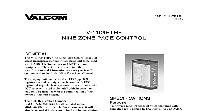
VSP V 1109RTVA 9 ZONE PAGE CONTROL V 1109RTVA Nine Zone Page Control is a dial microprocessor controlled page unit to be used PABX Electronic Key or 1A2 Telephone instructions contain the specifications and necessary to install operate and maintain Nine Zone Page Control paging unit has received an FCC type KX and is designed to be used with FCC key telephone systems Such installations be made by Valcom Inc telephone companies registered telephone installers of FCC registered under FCC Rules Section 68.215 accordance with FCC rules with applicable tariffs intercom unit may only be installed with the of the owner of the host system FCC Registration Number BAF9I7 69358 KX N be listed in the affidavits filed with the telephone it will also be recorded in the system log kept installation and maintenance personnel The local company is to be notified of the FCC Number when this intercom unit is equipment generates and uses radio frequency and if not installed and used properly that is in accordance with the manufacturer instructions cause interference to radio and television It has been tested and found to comply with limits for a Class B computing device in with the specifications in Subpart J of Part of the FCC Rules which are designed to provide protection against interference If this does cause interference to radio and reception which can be determined by the equipment off and on the user is to try to correct the interference by one or of the following measures Reorient the receiving antenna Relocate the equipment with respect to the Plug the equipment into a different branch circuit necessary the user should consult the dealer or an radio television technician for additional The user may find the following booklet by the Federal Communications Commission How to Identify and Resolve Radio TV Problems booklet is available from the US Government Office Washington DC 20402 Stock No provide nine 9 zones of voice announce with all to 1A2 Key E Key or PABX telephone systems Manuals Online key systems Electronic key system line key position PABX loop start trunk position page zones Built in preamplifier for one way page operation Dial tone Ringback tone Combined rotary and tone dialing Background music input and amplifier Built in all call Single digit dialing Off hook speaker inhibit 1A2 Off hook single digit redial push asterisk key The capacity of the V 1109RTVA is 9 zones and call One talkpath The maximum number of one way speaker assemblies is 40 per unless a V 1094A expander is used Plan dialing codes are 1 9 0 for all call Materials Required the time of installation the installer should provide following materials filtered power supply if existing supply not adequate type connecting block pair cable with a female amphenol connector one end Twisted pair cross connect wire x 5.9 W x 2.1 D H x 14.99cm W x 5.33cm D lbs 1.23 kg Requirements Valcom V 1109RTVA requires talk and signal battery The current and voltage range is shown in Table 1 TABLE 1 60 mA Battery Battery mA mA Lamp Battery to 26VDC to 25VDC 9 to 11VAC when working with telephone equipment BATTERY is NEGATIVE and GROUND is Characteristics operating parameters of the page control are listed Table 2 TABLE 2 Working Limits impedance Tip and Ring cable length to speaker Pulses Signals ohms ft audio pps break ratio 10 Standard dB ms Time ms to 50o C to 85 non precipitating section covers the installation procedures for the V 1109RTVA only Consult other equipment if additional equipment is used precautions have been taken at the factory to insure the equipment functions properly To insure operation and to prevent equipment damage observe the following Unplug the power supply before making any to the control unit Do not locate the control unit closer than 18 inches further than five feet from power supply Do not use a lamp tester to check signals use a A lamp tester when first applied is a circuit to electronic circuits Do not apply power to the control unit until all have been double checked Manuals Online the unit in a vacant space in an equipment rack or key system cabinet allowing enough at the rear of the unit to plug in an amphenol Mount a 66B type punchdown block near unit and label it per Figure 1 25 pair cable with a female connector should be run the unit to the connection block The cable be terminated on the connection block in color code order Verify that the connections correct prior to plugging the other end of the into the V 1109RTVA Page Unit to PABX System V 1109RTVA may be accessed by connecting the and BL W to the Tip and Ring respectively of a Start Trunk Circuit Refer to Figure 2 for to Electronic Key V 1109RTVA may be accessed by a C O line of an Electronic Key System by connecting the BL W of the V 1109RTVA to a spare line of the Electronic Key This line position must equipped with a trunk card Refer to Figure 2 for to 1A2 Key System V 1109RTVA may be connected to a spare button a 1A2 Key Telephone by making the following A 400 type line card is not needed in application W BL BL W of V 1109RTVA to spare button and Ring OR W to Lamp Lead of spare button for lamp W GN to Lamp Ground lead of spare button When the V 1109RTVA is connected to a Key System connect W OR to lamp battery or See Figure 3 For Meet Me Page on 1A2 connect A Leads spare button using 10K ohm resistors in series each A Lead The other side of resistors are to the BK GN inhibit of Refer to Figure 3 for connections Connections The V 1109RTVA is designed to use Connect the V BR lead to Talk Ground Connect the BR V lead to Talk Battery 24VDC Connect the V SL lead to Signal Ground Connect the SL V lead to Signal Battery 24VDC Connections outputs for paging zones start at the BK BR pair 1 through the V O pair zone 9 Refer to 3 for typical speaker connections using Valcom amplified speaker assemblies and Music Level Set up V 1109RTVA has volume controls for the functions Master Page Control located on back of unit amphenol connector All Call Master Control located on front of unit Background music input control Zones 1 5 Background music input control Zones 6 9 Set Up Master Page Control This control sets the level of the page out of the page control unit The control should be rotated clockwise to about 50 of its travel After setting control the individual speaker volume controls should be set to the desired level All Call Level The All call level should be set to produce the same audio level as the phone to speaker page control THIS ADJUSTMENT SHOULD BE MADE AFTER INDIVIDUAL SPEAKER LEVELS HAVE BEEN SET Background Music Levels There are two volume controls provided for background music adjustments Zones 1 5 and Zones 6 9 is important that the two background music controls used to set the music levels in the system Adjust controls after all other system volume levels have set THE MUSIC INPUT LEVEL FROM THE SOURCE SHOULD BE LIMITED TO