Valcom V-136RTHF

File Preview
Click below to download for free
Click below to download for free
File Data
| Name | valcom-v-136rthf-0714695238.pdf |
|---|---|
| Type | |
| Size | 936.53 KB |
| Downloads |
Text Preview
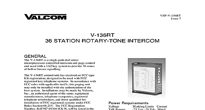
VSP V 136RTHF 6 ZONE TALKBACK INTERCOM CONTROL UNIT V 136RTHF is a single path dial select controlled intercom and page control used with a 1A2 key system or a PABX trunk to provide 36 zones of handsfree talkback V 136RTHF control unit has received an FCC KX registration designed to be used with FCC Key Telephone Systems In accordance FCC rules with applicable tariffs this Paging may only be installed with the authorization of host system Installations may be made by Inc an authorized agent of the same manufacturers telephone companies telephone refurbishers and those qualified installation of FCC registered systems under FCC Section 68.215 The FCC Registration BAF9I7 69358 KX N will be listed in the filed with the telephone company it will be recorded in the system log kept by installation maintenance personnel The local telephone is to be notified when this intercom unit is zone Dial tone Ringback tone Single or double signaling Combination rotary tone Last number dialed rering Dial rering tone mute Mixed bell and buzzer operation Mixed one way page and bell or buzzer Mixed two way handsfree page and bell or operation station one way page using one way speakers All call requires V 1134 and reduces number of to 34 Can be used with a variety of Valcom 45 ohm speakers and paging horns Plan The dialing codes are 0 5 39 Equipment Required Valcom 24 Vdc power supply 1A2 type power for buzzers Twisted pair cross connect wire Volt ohm milliammeter AWG power wire or cable and x 5.9 W x 2.1 D H x 14.99cm W x 5.33cm D lbs 1.6 Kg Requirements Limits Current Battery Battery Battery to Vdc 90 mA to Vdc 500 mA 9 to 11 Vac mA per lamp Manuals Online Characteristics Imp T and R Limits ohm incl inst Cable Length Way Page Page Pulses Signals DTMF feet feet PPS Break ratio 10 Time 40MS to 50o C to 85 precautions have been taken at the factory to that the equipment functions properly when correctly Please observe the following before applying power to the equipment the equipment may be damaged and the warranty a the key system power supply before any wires or cables from the connecting block With power accidental bridging of two terminals a wiring tool may damage electronic not locate the control unit more than five from the power supply not use a lamp tester to check signals in control unit Use a voltmeter A lamp when first applied is a short circuit to circuits not apply power to the control unit until connections have been double checked b c d runs to talkback speakers to not more 800 feet Do not split pairs all grounds common at power supply audio runs to one way speakers to not more 5000 feet Limit power runs to one way to maximum recommended for the particular type off hook speaker cancel circuit each ICM A must be connected through a 10K 1 4W 5 to the inhibit input W GR Refer to Figures and 3 When called station or any other party off hook the presence of two resistance grounds or turns off speaker Handsfree mode can be restored by terminating call and redialing the V 136RTHF on a 7 KTU mounting relay or on a wall The presence of a large field induced by some power supplies cause a loud 60 cycle hum on talk paths To or reduce hum mount control unit at least 12 power supply a 25 pair cable to the unit and terminate all on a 66 type block per Figure 1 2 or 3 Do not attempt to wire one group 10 29 or 0 5 9 30 39 for both bell buzzer and voice page Connections a When using 10 29 for bell buzzer signaling audible battery BR V to S1 IN b When using 0 5 9 and 30 39 for bell buzzer c connect audible battery to S2 IN bell buzzer return leads to audible from power supply Page Connections a When using 10 29 for voice page connect out V G to S1 IN V O b When using 0 5 9 and 30 39 for voice page speaker out V G to S 2 IN O V speaker return leads to speaker G V c to Figure 1 for programming options make a voice page go off hook and dial the of the desired zone or station Dial tone will broken after the first number is dialed A one ringback tone will indicate the called zone is signaled After the tone proceed with the page The called party may answer handsfree If the cancel circuit is wired refer to Installation called party goes off hook the speaker will be off Manuals Online rering the same station press the button The will be signaled as long as the button is held To rering using rotary dial dial 1 The station will signaled for one second each time a 1 is dialed achieve maximum performance from this system user should receive the following operating a calling party should speak directly into mouthpiece and avoid speaking softly called party must wait approximately second before responding to the calling b DESCRIPTION Method of Operation unit provides dial intercom access provisions to interface with the telephone system used A two way amplifier conditions the from the telephone system tip and ring and a low impedance low level output to the speaker via conventional telephone wiring house cable or station wire Description station user lifts handset to make an ICM page switchhook contacts in the telephone close the tip ring to form a loop which returns battery back to on transistor Q1 Transistor Q1 operates relay logic circuit to return dial tone and lamp battery telephone set Logic circuit receives dialing and operates relays and or circuitry to splash tone and a two way voice connection station selected When called or any other party off hook on ICM path the presence of two grounds cancels or turns off speakers if resistors are wired Handsfree mode can be restored by terminating call and redialing ASSISTANCE trouble is reported verify that All telephone sets are in proper working order Power is being supplied to the unit There are no broken connections at the block The conductors of color coded cables are in the proper order trouble still exists additional checks should be using the following equipment Voltmeter Tone dial single line instrument for tone dial Telephone Test Set Clip leads lamps must not be used to check voltages They damage electronic circuits A telephone test set not be used to check voltages the results will misleading proceeding further check the voltages at the block An undetected blown fuse or low will cause improper control operation DC measurements are made with respect to a spare unit is available continue to troubleshoot by the spare unit for the suspected unit If the has not been located refer to Table 1 Identify symptoms and perform the corrective actions After all the suggested tests have been the trouble still exists telephone Valcom at 540 427 3900 and ask for Technical Support call 540 427 6000 for Valcom 24 hour Automated or visit our website at equipment is not field repairable Valcom maintains service facilities in Roanoke VA repairs be necessary attach a tag to the unit stating company name address phone contact person and the nature of the Send the unit to Inc and Return Dept Hollins Road VA 24019 5056 Manuals Online Inc warrants its products to be free from defects in materials and workmanship under conditions of normal