Valcom v-2926
File Preview
Click below to download for free
Click below to download for free
File Data
| Name | valcom-v-2926-7802513649.pdf |
|---|---|
| Type | |
| Size | 1.38 MB |
| Downloads |
Text Preview
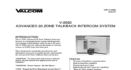
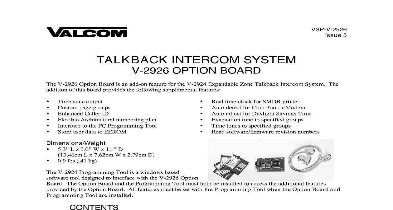
VSP V 2926 5 INTERCOM SYSTEM OPTION BOARD V 2926 Option Board is an add on feature for the V 2924 Expandable Zone Talkback Intercom System The of this board provides the following supplemental features Time sync output Custom page groups Enhanced Caller ID Flexible Architectural numbering plan to the PC Programming Tool Store user data to EEROM L x 3.0 W x 1.1 D L x 7.62cm W x 2.79cm D lbs 41 kg Real time clock for SMDR printer Auto detect for Com Port or Modem Auto adjust for Daylight Savings Time Evacuation tone to specified groups Time tones to specified groups Read software firmware revision numbers V 2924 Programming Tool is a windows based tool designed to interface with the V 2926 Option The Option Board and the Programming Tool must both be installed to access the additional features by the Option Board All features must be set with the Programming Tool when the Option Board and Tool are installed OF THE OPTION BOARD OF THE PROGRAMMING TOOL 1 Option Board Location on the Control Board THE PROGRAMMING TOOL Configuration Number and CLID Programming Connection of Service Page Groups Programmed Data to File WITH THE V 2924 Communications Direct Connect Modem Connect Dialing Method Modem Connect Manual Connect Data to V 2924 Receive Data from V 2924 System Date and Time Software and Firmware Revision Number Communications OF THE V 2924 MODEM OPTIONS Window Help Exit ASSISTANCE WARRANTY HARDWARE CONNECTIONS 2 2 3 4 4,5 6,7 7,8 8 9 Manuals Online OF THE OPTION BOARD Option Board must first be installed on the Control Unit Board See Figure 1 Disconnect main power before servicing Remove the side plate and top cover of the Control Unit and set aside Slide small side plate upward to provide opening for Option Board connector See Figure 1 Align J3 on the Option Board directly over J1 on the Control Board Align J4 on the Option Board directly over JP2 on the Control Board Press Option Board firmly in place to make sure connectors are seated properly Replace the top cover and side plate of the Control Unit and plug in the power supply Plug PC Communication Cable included into P1 PC Programming Port located on the Option Board See 1 V 2926 Option Board requires the use of the PC Programming Tool to access the various features it provides OF THE PROGRAMMING TOOL Computer Requirements for the Valcom V 2924 Programming Tool higher is recommended Hard drive with 30 Mbytes free Mouse Mbytes of RAM more is recommended available serial communication port System The Programming Tool is 32 bit and requires Windows 95 Windows 98 or Windows NT 4.0 Rev 2 Programming Tool is compatible with previous versions of hardware however the new hardware is compatible with previous versions of the Programming Tool programming tool software is furnished on 1.4 MB disks and must be installed to the hard drive To install the On the taskbar click the Start button disk 1 Select Run Type a Assuming a is the disk drive being used Follow on screen instructions for full installation changing disks as the prompt requests The Valcom V 2924 Programming Tool will automatically appear in the Programs list Manuals Online Manuals Online THE PROGRAMMING TOOL On the taskbar click the Start button point to Programs select Valcom V 2924 Programming Tool The V 2924 Programming Tool splash screen appears momentarily and then the Programming screen into view Configuration begin the programming process click on File A pull down menu appears allowing selection of a previously file click on Open or the ability to create a new file click on New The following instructions a New configuration file is being created Click on New from the pull down menu A System screen is displayed to allow selection of the installed components within the system one of the following from the list For a 24 station system select Main Board For a 48 station system select Main Board Expansion 1 For a 72 station system select Main Board Expansion 1 2 For a 96 station system select Main Board Expansion 1 2 3 OK to accept the present selection or Cancel to re select When selection is complete the Programming Screen will be displayed To display the configuration of the system press the Details button Manuals Online OK is selected from the System Configuration screen the Programming Window appears see below The Window allows each option to be accessed by selecting the option and pressing Open or by double on the selected option All functions can be listed at once by pressing Open All All of the options through the Programming Window can also be accessed from the pulldown menus Manuals Online Number and CLID Caller ID Programming first function to configure is the Architectural Number and CLID Programming Architectural Number is a 1 to 4 digit number that is dialed by the phone to connect to a specific speaker architectural numbering is often selected to allow speakers and room numbers to match The CLID allows a name or up to 15 character description to be entered for each station information entered in the CLID description field will be displayed on the phone or Caller ID unit if provided as of the system Edit Station Entry allows a CLID description to be entered for each station Example 105 would be the and MR HALL would be the CLID description 15 character limit Delete Station Entry allows removal of selected architectural and CLID descriptions Numbering assigns the Arch in sequential order The beginning number is the currently selected station an number must be specified Auto Number Highlight station where architectural numbering begins Edit Station Entry Enger beginning architectural number and select OK Auto Numbering and enter last architectural number must be a higher number OK information for the Main Board as well as each Expansion Unit being used and press OK to accept Manuals Online Connections screen allows selection of groups to receive Background Music Time Tones and Emergency Tones This system consists of a Board Expansion 1 so eight groups are available to receive audio connections group contains six stations 1 2 3 4 5 6 7 8 1 2 3 4 5 6 7 8 9 10 11 12 13 14 15 16 17 18 19 20 21 22 23 24 25 26 27 28 29 30 31 32 33 34 35 36 37 38 39 40 41 42 43 44 45 46 47 48 Board Board Board Board 1 1 1 1 on the tab of the desired feature to program zones Click on each group button to receive the audio If all groups are to receive an audio connection for the specific feature select Include All zones for each feature Time Tone and Emergency are selected in the same manner Tone All Off All On All On zones for each feature have been selected press the OK button Manuals Online Audio Connections screen disappears with the Programming Window still being active to allow selection of options of Service of Service defines how a call originated by a button press will be queued for answer by the attendant Emergency Only Top priority Stations programmed as Emergency Only are moved to the top of the priority to be answered first Normal Emergency Calls from stations programmed as Normal Emergency are received in the queue as they made 1 button press from the station the call is received as a normal call 4 button presses from the station call is received as an emergency call Normal Only Calls from stations programmed as Normal Only are received in the queue