Valcom v-9945a

File Preview
Click below to download for free
Click below to download for free
File Data
| Name | valcom-v-9945a-0263485791.pdf |
|---|---|
| Type | |
| Size | 991.07 KB |
| Downloads |
Text Preview
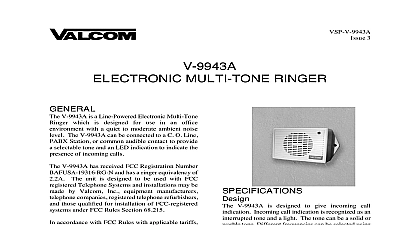
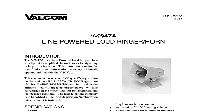
VSP V 9945A 6 TONE INTERRUPTED TONE LOUD HORN V 9945A is a horn with built in tone generator amplifier used for loud signaling applications instructions provide identification connection operation and maintenance information the V 9945A Single Tone Interrupted Warble Horn Ringer V 9945A provides amplified electronic tones for in large or noisy areas or outside Night ringing C O audible ringing Time clocks Special purpose signaling Self contained tone generator amplifier volume and horn speaker Single tone or warble tone outputs Power supply included Activated by dry contact closure Single tone will override warble tone Warble tone interrupted 1 second on 5 seconds Single tone continuous for duration of closure Weatherproof Units may be multipled for simultaneous access V 9945A has provisions for two inputs either or of which can be used in an application If both are activated simultaneously the single tone override the warble tone x 8.2 W x 10.4 D plus mounting bracket 16.51cm H x 20.83cm W x 26.42cm D lbs 1.95 kg Requirements to 26.0 Vdc B battery 250mA nominal Temperature Humidity to 55 degrees C to 95 non precipitating Requirements V 9945A requires a dry contact closure for of each tone If both tones will be used closures are required The closures may be in form of night ringing relay contacts time clock a standard normally open switch or Manuals Online to the following Table for speaker coverage first number given is the side to side distance for the speakers It is also the distance in front the speaker that you can expect to hear a good signal The second number is the area being in square feet Noisy ft ft 40 ft 20 ft Area sq ft sq ft 1,600 sq ft 400 sq ft Requirements system using the V 9945A will consist of the Access equipment See Design Section V 9945A Qty determined in Coverage Section power supply included with horn instructions cover only the installation for the Valcom V 9945A Please consult for other equipment if any other equipment being used SYSTEM RING CLOCK Speaker to Base For ease of installation the base can be to the speaker before or after the base is position adjustment knob the ball of the base into the socket of speaker the position adjustment knob V 9945A should be mounted 12 to 25 high in area requiring signaling The unit can be mounted a wall a beam or an electrical box the base to a wall using the two holes Knockout holes are provided for out should additional holes be C clamp is provided with the ringer to mounting to a beam Place the bolt the hole in the bottom of the base to the C clamp to the beam See 2 to an electrical backbox is by channeling wire through ball of the base see Figure 3 and appropriate connections The base holes punched for a double gang square but by punching out additional holes the base can be mounted to single gang or octagon box V 9945A may be rotated or moved up and down obtain the desired position by loosening the knob Figures 2 and 3 at the bottom of the unit 1 turn Make required adjustment and knob Vdc tone access tone access should be accomplished using twisted telephone wire The power supply should be within 500 ft of the horn negative 24 Vdc lead of the supply to the white lead connect Gnd lead of the power supply the black lead SUPPLY Designations 1 TYPICAL INSTALLATION precautions have been taken at the factory to that the equipment functions properly To proper operation and to prevent equipment please observe the following the power supply before making any to the unit not apply power to the unit until all have been double checked Manuals Online warble tone access connect contact between red and green single tone access connect contact between brown and green for both single tone and warble tones be made to the same speaker V 9945A is a horn speaker containing circuitry generate single and dual electronic tones as well as 5 watt amplifier and volume control It also a timer to interrupt the warble tone signal 1 on 5 seconds off When the red and green are connected together through a contact the warble tone and interrupter circuits are When the brown and green leads are the circuitry for the single tone is If both closures are applied the single tone be sent ASSISTANCE trouble is reported verify that power is being to the unit and there are no broken Check voltages for proper polarity on crossconnect block lineman test set several clip leads and a VOM be necessary to effectively troubleshoot the unit 1 identifies symptoms of some possible with solutions If your problem is listed the actions indicated the trouble has not been located continue to by substituting a spare unit for the unit in troubleshooting is available from the When calling you should have a VOM and a set available and be calling from the job site 540 427 3900 and ask for Technical Support call 540 427 6000 for Valcom 24 hour Support or visit our website at equipment is not field repairable Valcom maintains service facilities in Roanoke VA repairs be necessary attach a tag to the unit stating your company name address phone contact person and the nature of the Send the unit to Inc and Return Dept Hollins Road VA 24019 5056 1 Troubleshooting Chart No output Verify 24 volts on white lead and ground on black lead Verify volume control turned up clockwise Try shorting red and green or brown and green at horn and listen for output Manuals Online Inc warrants its products to be free from defects in materials and workmanship under conditions of normal use and service a period of one year from the date of shipment The obligation under this warranty shall be limited to the replacement repair or of any such defective device within the warranty period provided that LIMITED WARRANTY by Valcom Inc indicates the validity of the claim defect is not the result of damage misuse or negligence after the original shipment product has not been altered in any way or repaired by others and that factory sealed units are unopened A service plus parts and labor will be applied to units defaced or physically damaged charges for the return of products to Valcom are prepaid units of warranty are subject to a service charge The service charge will cover minor repairs Major repairs will be to additional charges for parts and labor warranty is in lieu of and excludes all other warranties expressed or implied and in no event shall Valcom Inc be for any anticipated profits consequential damages loss of time or other losses incurred by the buyer in connection the purchase operation or use of the product warranty specifically excludes damage incurred in shipment In the event a product is received in damaged condition the should be notified immediately Claims for such damage should be filed with the carrier involved in accordance with the point Inc Industry Avenue VA 24013 540 427 3900 540 427 3517 Canada Corporation Van Kirk Drive 11 and 12 Ontario L7A1A5 905 456 1072 905 456 2269 Clamp Base 2 Mount