Wheelock 31T horn installation sheet

File Preview
Click below to download for free
Click below to download for free
File Data
| Name | wheelock-31t-horn-installation-sheet-2065931874.pdf |
|---|---|
| Type | |
| Size | 793.73 KB |
| Downloads |
Text Preview
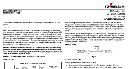
Branchport Ave Branch N J 07740 631 2148 Thank you for using our products INSTRUCTIONS this product according to this instruction manual Please keep this instruction manual for future reference offers a complete line of high performance AC horns Wheelock Horns are ideal for General Signaling Applications high output low current draw and dependability are of critical concern models provide rugged vandal resistant construction with die cast housing to protect the horn mechanism A full range of options are provided for indoor and outdoor installations All CAUTIONS and WARNINGS are identified by the symbol All warnings are printed in bold capital letters PLEASE READ THESE INSTRUCTIONS CAREFULLY FAILURE TO COMPLY WITH ANY OF THE INSTRUCTIONS CAUTIONS AND WARNINGS COULD RESULT IN IMPROPER APPLICATION AND OR OPERATION OF THESE PRODUCTS IN AN EMERGENCY SITUATION WHICH COULD RESULT PROPERTY DAMAGE SERIOUS INJURY OR DEATH TO YOU AND OR OTHERS THE 31T HORN APPLIANCE IS A ALARM DEVICE DO NOT PAINT 1 Ratings Per UL Current UL 464 FOR UL APPLICATIONS THESE APPLIANCES WERE TESTED TO THE OPERATING VOLTAGE LIMITS 96 132 VOLTS DO NOT APPLY 80 AND 110 OF THESE VOLTAGE VALUES FOR SYSTEM OPERATION MAKE SURE THAT THE TOTAL RMS CURRENT REQUIRED BY ALL APPLIANCES THAT ARE TO THE SYSTEM PRIMARY AND SECONDARY POWER SOURCES DO NOT EXCEED THE POWER RATED CAPACITY OR THE CURRENT RATINGS OF ANY FUSES ON THE CIRCUITS TO WHICH THESE ARE WIRED OVERLOADING POWER SOURCES OR EXCEEDING FUSE RATINGS COULD RESULT IN OF POWER AND FAILURE TO ALERT OCCUPANTS DURING AN EMERGENCY WHICH COULD RESULT IN DAMAGE AND SERIOUS INJURY OR DEATH TO YOU AND OR OTHERS calculating the total currents Use Table 1 to determine the highest value of Current for an individual horn across expected operating voltage range of the horn then multiply these values by the total number of horns be sure to add the for any other appliances including audible signaling appliances powered by the same source and include any required factors DIAGRAM 1 2 Typical Wiring PRECEDING APPLIANCE ALARM CONTROL PANEL FACP TO NEXT APPLIANCE OR OF LINE EOLR 2004 Wheelock Inc All rights reserved AC 1 of 4 OPTIONS The following figures show the maximum number of field wires conductors that can enter the backbox used each mounting option If these limits are exceeded there may be insufficient space in the backbox to accommodate the wires and stresses from the wires could damage the product the limits shown for each mounting option comply with the National Electrical Code NEC Wheelock recommends of the largest backbox option shown and the use of approved stranded field wires whenever possible to provide additional room for easy installation and minimum stress on the product from wiring HORN MOUNTING BACKBOX BE MOUNTED WALL HORN BASIC HORN IS SUPPLIED SCREW TERMINALS FOR TO THE POWER 2 10 32 SCREWS ACCESSORIES TO THE UNIT IF REQUIRED AND 8 32 SCREWS FOR IF NO ACCESSORIES ARE REQUIRING THESE INSERT THEM INTO UNUSED HOLES RESISTANT MOUNTING RESISTANT TO BE IN WALL CONDUIT TOP PLATE WITH 10 32 AND 8 32 SCREWS NUMBER OF CONDUCTORS 18 AWG 16 AWG 14 AWG 12 MOUNTING 4 SQUARE TO BE IN WALL PLATE 2 8 32 HORN HORN 8 32 SCREWS NUMBER OF CONDUCTORS 18 AWG 16 AWG 14 AWG 12 CONDUIT MOUNTING BOX WALL PLATE WITH 8 32 6 32 BUSHING 4 BACKBOX 10 32 8 32 SCREWS NUMBER OF CONDUCTORS 18 AWG 16 AWG 14 AWG 12 SURFACE MOUNTING 4 SQUARE TO BE ON WALL HORN 10 32 HORN 8 32 SCREWS NUMBER OF CONDUCTORS 18 AWG 16 AWG 14 AWG 12 10 32 8 32 SCREWS NUMBER OF CONDUCTORS 18 AWG 16 AWG 14 AWG 12 AC 2 of 4 PROCEDURES If sheathed multiconductor cable or 3 4 conduit fittings are used check that installed product has sufficient and wiring room prior to installing backboxes and conduit weather resistant installation use outdoor mounting option see Mounting Option B Outdoor backbox must be vertically with TOP as marked to allow any moisture or condensation to drain properly through drain holes on of backbox Operate only within specified voltage range for rated performance and endurance All horns will operate on coded systems up to 3 on off cycles per second Anechoic dB ratings are for free field anechoic conditions Such conditions are approximated in outdoor installations installations provide greater dB because of reflected sound energy terminals with wire clamps 2 leads 12 22 American Wire Guage AWG wire per position are allowed Strip approximately 3 8 for connection to terminals Break wire run to provide electrical supervision largest backbox shown in Mounting Options where possible to provide additional wiring room for easy installation Conduit entrance to backboxes should be selected to insure sufficient wiring clearance for installed equipment When rings are required conduit should enter through backbox not extension ring Use Steel City 53151 1 1 2 deep 53171 2 1 8 deep extension rings or equal with same area cut out in back Backboxes for all horns should be securely mounted Looseness may degrade sound output If these appliances are operated within 15 inches of a person ear they can produce a sound pressure level that the maximum 120dBA permitted by ADA and OSHA rules Exposure to such sound levels can result in damage to a hearing Check the installation instructions of the manufacturers of other equipment used in the system for any or restrictions on wiring and or locating Notification Appliance Circuits NAC and notification appliances Some communication circuits and or audio circuits for example may require special precautions to assure electrical noise e g audio crosstalk MATERIAL EXTRAPOLATED FROM THIS DOCUMENT OR FROM WHEELOCK MANUALS OR OTHER DESCRIBING THE PRODUCT FOR USE IN PROMOTIONAL OR ADVERTISING CLAIMS OR ANY OTHER USE INCLUDING DESCRIPTION OF THE PRODUCT APPLICATION OPERATION AND TESTING IS USED AT THE SOLE RISK OF THE USER AND WHEELOCK WILL NOT ANY LIABILITY FOR SUCH USE READ SEPARATE GENERAL INFORMATION SHEET FOR INFORMATION ON THE LIMITATIONS INSTALLATION FINAL CHECKOUT AND PERIODIC TESTING OF APPLIANCES AC 3 of 4 Warranty products must be used within their published specifications and must be PROPERLY specified applied installed maintained and operationally tested in accordance with these instructions at the time of installation and at least twice a or more often and in accordance with local state and federal codes regulations and laws Specification application operation maintenance and testing must be performed by qualified personnel for proper operation in accordance all of the latest National Fire Protection Association NFPA Underwriters Laboratories UL Underwriters Laboratories Canada ULC National Electrical Code NEC Occupational Safety and Health Administration OSHA local state province district federal and other applicable building and fire standards guidelines regulations laws and codes but not limited to all appendices and amendments and the requirements of the local authority having jurisdiction Wheelock products when properly specified applied installed operated maintained and operationally tested as a