Wheelock 43T bells install sheet P10352V

File Preview
Click below to download for free
Click below to download for free
File Data
| Name | wheelock-43t-bells-install-sheet-p10352v-6159782430.pdf |
|---|---|
| Type | |
| Size | 718.48 KB |
| Downloads |
Text Preview
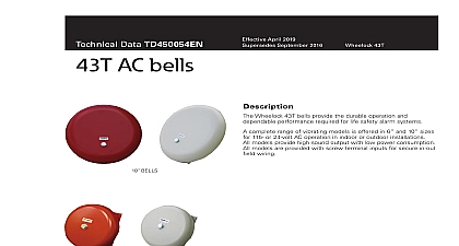
Branchport Ave Branch N J 07740 631 2148 USA 397 5777 CANADA Thank you for using our products INSTRUCTIONS BELLS this product according to this instruction manual Please keep this instruction manual for future reference 43T Bell Series is UL Listed under Standard 464 for Audible Signal Appliances The 43T Bell Series is also ULC Listed under Standard for Audible Signaling Appliances The Bell design features low power consumption with a high sound output and suppression to minimize the RFI generated by the contacts The Bells are available in either an AC model for indoor or outdoor use vibrating modes Models are available with a 6 or 10 gong as shown below The various mounting options available for the Bell Series for a convenient and economical installation The 43T Bell is suitable for outdoor use with the WBB Weatherproof backbox see Option D All CAUTIONS and WARNINGS are identified by the symbol All warnings are printed in bold capital letters PLEASE READ THESE INSTRUCTIONS CAREFULLY FAILURE TO COMPLY WITH ANY OF THE INSTRUCTIONS CAUTIONS AND WARNINGS COULD RESULT IN IMPROPER APPLICATION AND OR OPERATION OF THESE PRODUCTS IN AN EMERGENCY SITUATION WHICH COULD RESULT PROPERTY DAMAGE SERIOUS INJURY OR DEATH TO YOU AND OR OTHERS THE 43T HORN APPLIANCE IS A ALARM DEVICE DO NOT PAINT 6 6 1 Ratings Per UL ULC RMS at 10 Feet 464 2B ULC Directional Characteristics degrees left and right degrees left and right degrees up and down degrees up and down FOR UL ULC APPLICATIONS THESE APPLIANCES WERE TESTED TO THE OPERATING VOLTAGE OF 16 33 VOLTS FOR 24V MODELS OR 96 132V FOR 115V MODELS DO NOT APPLY 80 AND 110 OF THESE VALUES FOR SYSTEM OPERATION MAKE SURE THAT THE TOTAL RMS CURRENT REQUIRED BY ALL APPLIANCES THAT ARE TO THE SYSTEM PRIMARY AND SECONDARY POWER SOURCES DO NOT EXCEED THE POWER RATED CAPACITY OR THE CURRENT RATINGS OF ANY FUSES ON THE CIRCUITS TO WHICH THESE ARE WIRED OVERLOADING POWER SOURCES OR EXCEEDING FUSE RATINGS COULD RESULT IN OF POWER AND FAILURE TO ALERT OCCUPANTS DURING AN EMERGENCY WHICH COULD RESULT IN DAMAGE AND SERIOUS INJURY OR DEATH TO YOU AND OR OTHERS calculating the total currents Use Table 1 to determine the highest value of Current for an individual bell across the expected voltage range of the bell then multiply these values by the total number of bells be sure to add the currents for any other appliances by the same source and include any required safety factors CHECK THE MINIMUM AND MAXIMUM OUTPUT OF THE POWER SUPPLY AND STANDBY BATTERY SUBTRACT THE VOLTAGE DROP FROM THE CIRCUIT WIRING RESISTANCE TO DETERMINE THE APPLIED TO THE SIGNALING APPLIANCE 2009 Cooper Wheelock Inc dba Cooper Notification All rights reserved V 1 of 3 DIAGRAM NEXT SIGNAL OR OF LINE RESISTOR SIGNAL OR ALARM CONTROL bell shell Do not mix shells from other units Wiring Refer to Wiring Diagram Bell To Backbox Using Screws Supplied With Unit Bell Shell Note keyhole alignment UNITS ARE SUPPLIED 4 SCREW TERMINALS CONNECTION TO THE SOURCE 8 32 SCREWS ARE WITH EACH MOUNTING PIN Wiring method shall be in accordance with CSA C22.1 Canadian Electrical Code Part 1 Safety Standard for Electrical Installations 32 OPTIONS BELL SHELL MOUNTING BELL 6 OR 10 SHELL MOUNTING 4 SQUARE TO BE IN WALL PLATE 8 32 SCREWS BELL SURFACE MOUNTING CONDUIT MOUNTING 4 BACKBOX BE MOUNTED WALL SURFACE PLATE WITH 6 32 BUSHING BOX WALL BELL BELL PIN PIN HOLE GUIDE PIN PIN 8 32 SCREWS NUMBER OF CONDUCTORS 18 AWG 16 AWG 14 AWG 12 RESISTANT MOUNTING RESISTANT TO BE ON SURFACE CONDUIT TOP PIN PIN SCREWS NUMBER OF CONDUCTORS 18 AWG 16 AWG 14 AWG 12 SCREWS BELL 8 32 SCREWS NUMBER OF CONDUCTORS 18 AWG 16 AWG 14 AWG 12 NUMBER OF CONDUCTORS 18 AWG 16 AWG 14 AWG 12 Suitable for outdoor use with the WBB Weatherproof backbox see Mounting Option D PROCEDURES weather resistant installation use outdoor mounting option Outdoor backbox must be mounted vertically with TOP as marked to any moisture or condensation to drain properly through drain holes on bottom of backbox bell mechanism is adjusted to operate only with the shell provided Do not mix shells and mechanisms during installation Do not bell mechanisms during installation input terminal accepts one lead for in out wiring of 12 22 AWG wire Strip wire leads approximately 1 2 for connection to Break wire run to provide electrical supervision bells will operate on coded systems up to 2 on off cycles per second polarity shown in the wiring diagram is for proper operation of the appliances in alarm mode For supervision mode the polarity be reversed Anechoic dB ratings are for free field anechoic conditions Typical indoor sound output is usually higher than rated anechoic dB for all bells should be securely mounted Looseness may degrade sound output Conduit entrance to backboxes should be to insure sufficient wiring clearance V 2 of 3 MATERIAL EXTRAPOLATED FROM THIS DOCUMENT OR FROM COOPER NOTIFICATION MANUALS OR OTHER DESCRIBING THE PRODUCT FOR USE IN PROMOTIONAL OR ADVERTISING CLAIMS OR FOR ANY USE INCLUDING DESCRIPTION OF THE PRODUCT APPLICATION OPERATION INSTALLATION AND IS USED AT THE SOLE RISK OF THE USER AND COOPER NOTIFICATION WILL NOT HAVE ANY LIABILITY SUCH USE WARRANTY Wheelock Inc dba Cooper Notification and Cooper Notification Inc each a products must be used within their published and must be PROPERLY specified applied installed operated maintained and operationally tested in accordance with these at the time of installation and at least twice a year or more often and in accordance with local state and federal codes regulations laws Specification application installation operation maintenance and testing must be performed by qualified personnel for proper in accordance with all of the latest National Fire Protection Association NFPA Underwriter Laboratories UL National Code NEC Occupational Safety and Health Administration OSHA local state county province district federal and other building and fire standards guidelines regulations laws and codes including but not limited to all appendices and amendments and requirements of the local authority having jurisdiction AHJ Seller products when properly specified applied installed operated and operationally tested as provided above are warranted against mechanical and electrical defects for a period of a three 3 years date of manufacture with respect to MEDC and Seller Industrial Signals and Seller Fire and Security Notification Appliances and or b one 1 year from date of manufacture with respect to Waves and SafePath Voice Evacuation and Mass Notification Systems of manufacture is determined by date code Correction of defects by repair or replacement shall be at Seller sole discretion and shall fulfillment of all obligations under this warranty THE FOREGOING LIMITED WARRANTY SHALL IMMEDIATELY IN THE EVEN