Wheelock AMT horn strobe installation sheet P84158

File Preview
Click below to download for free
Click below to download for free
File Data
| Name | wheelock-amt-horn-strobe-installation-sheet-p84158-7296381405.pdf |
|---|---|
| Type | |
| Size | 850.06 KB |
| Downloads |
Text Preview
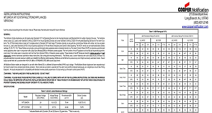
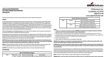
Branchport Avenue Branch NJ 07740 631 2148 USA 397 5777 CANADA Thank you for using our products SERIES AMT MULTITONE STROBE APPLIANCE INSTALLATION INSTRUCTIONS this product according to this instruction manual Please keep this instruction manual for future reference AMT Multitone Strobe Appliance is UL Listed under Standard 1971 for Emergency Appliances for the Hearing Impaired and UL Standard 464 for Appliances Model AMT 24MCW is also ULC Listed under Standard CAN ULC S526 07 for Visual Signaling and under Standard CAN ULC for Audible Signal Devices for Fire Alarm Systems Models with amber blue green and red lens are UL Listed under Standard UL1638 Visual Appliance for Private Mode Emergency and General Utility Signaling The AMT Strobes can provide a non synchronized strobe appliance connected directly to a Fire Alarm Control Panel FACP or provide a synchronized strobe appliance when used in conjunction with a Sync Module Dual Sync Module DSM or Wheelock power supplies They are listed for wall mount only with the backboxes specified in these instructions wiring and mounting information Models with 1575W strobes are listed at 15 candela under UL Standard 1971 and meet 75 candela intensity on with low current draw The 24MCW model strobe can provide 4 selectable candela settings 15 30 75 110 The AMT Multitone Strobe use a xenon flashtube with solid state circuitry enclosed in a polycarbonate lens to provide maximum visibility and reliability for effective signaling Notification AMT Appliances are unique multitone alarm signals with separate input terminals for each sound They are the ideal choice for systems and emergency signaling systems where distinctive multiple alarm conditions are required Eight groups of three self prioritized outputs are provided with separate electrically isolated input terminals for each sound see Table 2 and Table 8 for sound selections Sound can be field set to provide either HIGH HI dBA or STANDARD STD dBA sound output level AMT Multitone Strobe models are designed for use with either filtered or unfiltered Full Wave Rectified FWR input voltage The AMT Multitone Appliances have separate input terminals for alarm tone activation and strobe activation The strobes can be easily field programmed to operate or in unison with all of the audible alarms All inputs are polarized for compatibility with standard reverse polarity supervision of circuit by a fire alarm control panel FACP All Canadian Installations should be in accordance with the Canadian Standard for the Installation of Fire Alarm Systems CAN ULC S524 and Electrical Code Part 1 Final acceptance is subject to Authorities Having Jurisdiction PLEASE READ THESE INSTRUCTIONS CAREFULLY BEFORE USING THIS PRODUCT FAILURE TO COMPLY WITH ANY OF FOLLOWING INSTRUCTIONS CAUTIONS AND WARNINGS COULD RESULT IN IMPROPER APPLICATION INSTALLATION AND OR OF THESE PRODUCTS IN AN EMERGENCY SITUATION WHICH COULD RESULT IN PROPERTY DAMAGE AND SERIOUS INJURY DEATH TO YOU AND OR OTHERS 1 UL ULC Listed Models Ratings at 10 Feet Candela 10 Feet 1575 models are Listed at 15cd and meet 75 on axis Ratings at 10 Feet 10 Feet Strobes will produce 1 flash per second over the Voltage Range Strobe with clear lens meet the required light distribution patterns defined in UL 1971 and ULC S526 07 Strobes with amber lens meet the light distribution patterns per UL 1971 All models are UL Listed for indoor use with a temperature range of 32 to 120 0 to 49 and maximum humidity of 93 2 RH The of shipping and storage temperatures do not adversely affect the performance of the appliances when stored in the original cartons and are subjected to misuse Candela ratings in Table 1 are rated for clear lens Derate approximately 25 for amber 55 for green 70 for blue and 80 for red Time Horn 3 Horn 3 Tone Whoop Chime 2 Ratings for AMT Multitone Audible Signals Description Horn Continuous Modulated 0.07 Sec ON Repeat 0.25 Sec ON 0.25 Sec OFF Repeat ANSI S3.41 Temporal Pattern ANSI S3.41 Temporal Pattern Sweep 4.0 Sec ON 0.5 Sec OFF Repeat Sweep 1.0 Sec ON Repeat 0.25 Sec ON Alternate 1.0 Sec Decay Repeat For ULC applications only Code 3 Horn and Code 3 Tone are required to meet the ULC minimum of 85 dBA and the audible signal temporal mandated by the National Building Code of Canada 2009 Cooper Wheelock Inc dba Cooper Notification All rights reserved P84158 M 1 of 9 FOR UL ULC APPLICATIONS THESE APPLIANCES WERE TESTED TO THE REGULATED VOLTAGE LIMITS OF 16.0 33.0 FOR 24V MODELS USING FILTERED DC OR UNFILTERED FULL WAVE RECTIFIED VOLTAGE DO NOT APPLY VOLTAGE OUTSIDE OF RANGE CHECK THE MINIMUM AND MAXIMUM OUTPUT OF THE POWER SUPPLY AND STANDBY BATTERY AND SUBTRACT THE DROP FROM THE CIRCUIT WIRING RESISTANCE TO DETERMINE THE APPLIED VOLTAGE TO THE STROBES THE MAXIMUM IMPEDENCE BETWEEN STROBES SHALL NOT EXCEED 35 OHMS Tables 3 3A 4 and 4A to determine the highest value of Current for an individual AMT strobe across the expected operating voltage of the AMT strobe Add strobe current from Table 3 or 3A to audible appliance current from Table 2 and 2A to obtain total current for each unit if strobe and audible are wired to operate in unison on a single circuit Be sure to add the currents for any other appliances including audible signaling powered by the same source and include any required safety factors The maximum number of strobes on a single notification appliance circuit shall not exceed 50 3 UL Current Ratings for Horn Only AMPS HI LO RMS Current Per UL 464 3 3 3A Current Ratings for AMT Multitone Audible Appliances Time Horn 3 Horn 3 Tone Whoop Chime Horn Continuous Hz Modulated 0.07 Sec ON Repeat 0.25 Sec ON 0.25 Sec OFF Repeat ANSI S3.41 Temporal Pattern Hz ANSI S3.41 Temporal Pattern Sweep 4.0 Sec ON 0.5 Sec OFF Repeat Sweep 1.0 Sec ON Repeat Hz 0.25 Sec ON Alternate 1.0 Sec Decay Repeat RMS Current CANDELA SETTING WILL DETERMINE THE CURRENT DRAW OF THE PRODUCT 4 Current Ratings for 24MCW Strobe Only Voltage RMS Current AMPS Voltage 4A UL Current Ratings for 241575W Strobe Only RMS Current AMPS Voltage M 2 of 9 MAKE SURE THAT THE TOTAL RMS CURRENT REQUIRED BY ALL APPLIANCES THAT ARE CONNECTED TO THE SYSTEM AND SECONDARY POWER SOURCES APPLIANCE CIRCUITS SM DSM SYNC MODULES AND WHEELOCK POWER SUPPLIES NOT EXCEED THE POWER SOURCES RATED CAPACITY OR THE CURRENT RATINGS OF ANY FUSES ON THE CIRCUITS TO WHICH APPLIANCES ARE WIRED OVERLOADING POWER SOURCES OR EXCEEDING FUSE RATINGS COULD RESULT IN LOSS OF POW