Wheelock CH Chimes Install Sheet P83599

File Preview
Click below to download for free
Click below to download for free
File Data
| Name | wheelock-ch-chimes-install-sheet-p83599-8960153247.pdf |
|---|---|
| Type | |
| Size | 957.81 KB |
| Downloads |
Text Preview
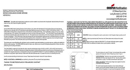
INSTALLATION INSTRUCTIONS CH70 CH90 ELECTRONIC CHIMES 2 Series CH70 90 Electronic Chimes are UL Listed under Standard 1971 for Signaling Devices for the Hearing Impaired and UL Standard for Private Mode Audible Signal Appliances as well as CAN ULC S525 16 CH70 90 Chimes are designed for low current draw and performance All models offer a choice of 1Hz 2Hz coded or temporal code 3 T3 operation have adjustable sound level and a chime tone of 890Hz The Series CH70 90 appliances also incorporate a chime mounting plate attached to the chime for ease of in CH70 and CH90 Chime models can provide a non synchronized strobe appliance when connected directly to a fire alarm control FACP or provide a synchronized strobe appliance when used in conjunction with a Dual Sync Module DSM and Cooper Wheelock supplies The CH70 and CH90 Chimes are for wall or ceiling mounting All models are Listed for indoor use only with the backboxes in these instructions see wiring and mounting information In Canada this device is for Dwelling Use Only this product according to this instruction manual Please keep this instruction manual for future reference All CAUTIONS and WARNINGS are identified by the symbol and printed in bold capital letters THE CHIME APPLIANCE IS A ALARM DEVICE DO NOT PAINT The Code 3 temporal pattern 1 2 second on 1 2 second off 1 2 second on 1 2 second off 1 2 second on 1 1 2 off and repeat is by ANSI and NFPA 72 for standard emergency evacuation signaling In order to synchronize the Chime tone the Chime device must NOT be set for coded operation see table 2 for switch settings All available in red or white 1 UL ULC Listed Models and Ratings Operating Voltage VRMS RMS Max A dBA at 10 Feet dBA at 10ft Min AND MOUNTING INFORMATION Check that the installed product will have sufficient clearance and wiring room prior to installing backboxes and conduit if sheathed multiconductor cable or 3 4 conduit fittings are used the limits shown for each mounting option comply with the National Electrical Code NEC Cooper Wheelock recommends use the largest backbox option shown and the use of approved stranded field wires whenever possible to provide additional wiring room for installation and minimum stress on the product from wiring Chime model has in out wiring terminals that accept two 12 to 18 American Wire Gauge AWG wires at each screw terminal Strip 3 8 inches and connect to screw terminals as shown in Figure 1 Figure 3 all in out wire runs on supervised circuits to assure integrity of circuit supervision as shown in Figure 2 The polarity shown in the diagrams is for operation of the appliances The polarity is reversed by the FACP during supervision 1 Figure 2 MAKE SURE THAT THE TOTAL RMS CURRENT REQUIRED BY ALL APPLIANCES THAT ARE CONNECTED TO THE PRIMARY AND SECONDARY POWER SOURCES DO NOT EXCEED THE POWER SOURCES RATED CAPACITY OR THE RATINGS OF ANY FUSES ON THE CIRCUITS TO WHICH THESE APPLIANCES ARE WIRED OVERLOADING POWER OR EXCEEDING FUSE RATINGS COULD RESULT IN LOSS OF POWER AND FAILURE TO ALERT OCCUPANTS DURING EMERGENCY WHICH COULD RESULT IN PROPERTY DAMAGE AND SERIOUS INJURY OR DEATH TO YOU AND OR OTHERS 2 Chime Tone Settings SW1 Position 2 3 T3 chime is factory set in code 3 T3 mode It can be changed before the appliance with the dip switch Refer to PC Board layout shown Figure 3 OPERATION The minimum input pulse duration must be at 160 milliseconds time and 160 milliseconds time The will only operate once each time it is pulsed This mode is recom for coded systems 3 1HZ AND 2HZ Continuous input voltage must be applied to chime to activate the chime in these modes volume and tone controls have been adjusted at the factory to insure dBA output However once the mode is selected the installer want to fine tune the appliance to better suit the application a synchronized tone application the Chime will default to temporal 3 no matter what the DIP switches are set to cannot be set to model is UL ULC Listed for indoor use with a temperature range of 32 to 122 0 to 50 and maximum humidity of 93 The effect of shipping and storage temperatures shall not adversely affect the performance of the appliance when it is stored in the cartons and is not subjected to misuse or abuse chime must be set at maximum volume for Dwelling Use listing requirements chime produces a brief inrush current of 0.100 Amps with filtered DC input 0.140 Amps with full wave rectified VRMS input with duration of 100 milliseconds P83599P273 Branchport Ave Long Branch N J 07740 800 631 2148Copyright 2018 Cooper Wheelock Inc dba Cooper Notification All rights reserved firealarmresources com These notification appliances are UL ULC Listed as They are intended to be used with FACPs whose notification circuits are UL ULC Listed These appliances shall not be used on UL ULC Listed Application notification circuits unless the appliances are identified to be compatible in the instructions of the FACP or unless the FACP is identified to be compatible in this instruction manual Figure 4 5 Install the appliance to a grounded backbox Per NFPA 70 the National Electrical Code using the lockwashers provided in bag under the head of each mounting screw for the appliance PROCEDURES The following figures 4,5 show the maximum number of field wires conductors that can enter the backbox used with each option If these limits are exceeded there may be insufficient space in the backbox to accommodate the field wires and stresses the wires could damage the product model can be flush mounted to a 4 square by 2 1 8 deep backbox with a 4 square 1 1 2 extension ring or surface mounted to a Surface Backbox Figure 5 hardware for each mounting option is supplied entrances to the backbox should be selected to provide sufficient wiring clearance for the installed product Do not pass additional wires used for other than the appliance through the backbox Such additional wires could result in insufficient wiring space for the signaling appliance terminating field wires do not use more lead length than required Excess lead length could result in insufficient wiring space for the signaling appliance care and proper techniques to position the field wires in the backbox so that they use minimum space and produce minimum stress on the product This is espe important for stiff heavy gauge wires and wires with thick insulation or sheathing the chime mounting plate to the backbox with the cone protector on After the chime mounting plate is attached to the backbox remove the cone protector before the grille Next attach the grille to the chime mounting plate and attach with 2 screws THESE APPLIANCES WERE TESTED TO THE REGULATED VOLTAGE LIMITS OF 16.0 33.0 VOLTS FOR 24V MODELS USING FILTERED DC OR FULL WAVE RECTIFIED VOLTAGE DO NOT APPLY VOLTAGE OUTSIDE OF THIS RANGE PLEASE READ THESE INSTRUCTIONS CAREFULLY FAILURE TO COMPLY WITH ANY OF THE FOLLOWING INSTRUCTIONS CAUTIONS AND COULD RESULT IN IMPROPER APPLICATION INSTALLATION AND OR OPERATION OF THESE PRODUCTS IN AN EMERGENCY SITUATION COULD RESULT IN PROPERTY DAMAGE AND SERIOUS INJURY OR DEATH TO YOU AND OR OTHERS equipment has been tested and found to comply with the limits for a Class A digital device pursuant to part 15 of the FCC Rules limits are designed to provide reasonable protection against harmful interference when the equipment is operated in a commercial This equipment generates uses and can radiate radio frequency energy and if not installed and used in accordance with the manual may cause harmful interference to radio communications Operation of this equipment in a residential area is likely to harmful interference in which case the user will be required to correct the interference at his own expense Class A digital apparatus meets all requirements of the Canadian Interference Causing Equipment Regulations Cet appareil num de la classe A respecte toutes les exigences du R sur le mat brouilleur du Canada MATERIAL EXTRAPOLATED FROM THIS DOCUMENT OR FROM COOPER NOTIFICATION MANUALS OR OTHER DOCUMENTS DESCRIBING THE PRODUCT USE IN PROMOTIONAL OR ADVERTISING CLAIMS OR FOR ANY OTHER USE INCLUDING DESCRIPTION OF THE PRODUCT APPLICATION OPERATION


