Wheelock E70 E90 ceiling speaker strobe install sheet P84398

File Preview
Click below to download for free
Click below to download for free
File Data
| Name | wheelock-e70-e90-ceiling-speaker-strobe-install-sheet-p84398-4759628310.pdf |
|---|---|
| Type | |
| Size | 1009.80 KB |
| Downloads |
Text Preview
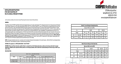
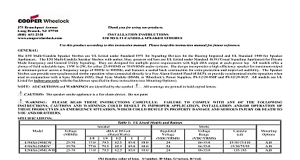
INSTALLATION INSTRUCTIONS E70 24MCC AND E90 24MCC SPEAKER STROBE MOUNT this product according to this instruction sheet Please keep this instruction sheet for future reference E70 24MCC and E90 24MCC Multi Candela Speaker Strobes are UL Listed under Standard 1971 for Signaling Devices for the Impaired for indoor fire protection service E70 24MCC and E90 24MCC are designed for multiple power requirements with high output at each power tap and offers a choice of field selectable taps 1 8W to 2W for either 25.0VRMS or 70.0VRMS audio systems strobes with amber red blue or green lens are UL Listed under Standard UL1638 Visual Signaling Appliance for Private Mode and General Utility Signaling The low profile design incorporates a high efficiency speaker for maximum output at minimum across a frequency range of 400Hz to 4000Hz and features a sealed back construction for extra protection and improved audibility Series E70 24MCC and E90 24MCC Multi Candela provides four selectable light output intensities in one unit and incorporates a mounting plate attached to the speaker for ease of installation The low profile speaker strobe can provide a non synchronized appliance when connected directly to a Fire Alarm Control Panel FACP or provide a synchronized strobe appliance when used in with a Sync Module SM Dual Sync Module DSM or Cooper Wheelock power supplies The Strobes use a Xenon flashtube solid state circuitry enclosed in a polycarbonate lens to provide maximum visibility and reliability for effective visible signaling The E70 24MCC and E90 24MCC are Listed for indoor use ceiling mount only with the backboxes specified in these instructions see and mounting information Please read these instructions carefully Failure to comply with any of the following instructions cautions and warn could result in improper application candela setting installation and or operation of these products in an emergency situa which could result in property damage and serious injury or death to you and or others 1 UL Listed Models and Ratings at 10 Feet Watts The strobe produces 1 flash per second over the Regulated Voltage range Strobes with clear and amber lens meet the required light distribution patterns defined in UL 1971 The E70 90 24MCC is UL Listed for indoor use with a temperature range of 32 to 120 0 to 49 and maximum humidity 85 RH The effect of shipping and storage temperatures shall not adversely affect the performance of the appliance when it is in the original cartons and is not subjected to misuse or abuse The maximum supervision voltage is 33 volts DC Frequency range of speakers is 400 4000Hz Candela ratings listed in Table 1 are for clear lens Derate approximately 25 for amber lens 55 for green lens 70 for blue lens 80 for red lens Always operate audio amplifiers and speakers within their specified ratings Excessive input may distort sound quality and damage audio equipment Do not exceed 100 of speaker input voltage per UL 1480 Improper input voltage can damage speaker distortion is heard check for clipping of the audio appliance with an oscilloscope and reduce the amplifier input level or gain level to any clipping Candela setting determines the current draw of the product calculating the total currents use Table 2 to determine the highest value of RMS current for an individual strobe then multiply these by the total number of strobes Be sure to add the currents for any other appliances including audible signaling appliances pow by the same source and to include any required safety factors The maximum number of strobes on a single notification appliance circuit shall not exceed 50 These strobes are UL Listed as Regulated They are intended to be used with FACPs whose notification circuits are UL Listed Regulated These appliances shall not be used on UL Listed Special Application notification circuits unless the appliances are identified be compatible in the installation instructions of the FACP or unless the FACP is identified to be compatible in this instruction manual These strobes were tested to the regulated voltage limits of 16.0 33.0 Volts for 24V models using filtered DC or unfil full wave rectified voltage Do not apply voltage outside of this range Verify the minimum and maximum output of the power supply and standby battery and subtract the voltage drop from circuit wiring resistance to determine the applied voltage to the strobes The maximum wire impedance between strobes shall exceed 35 ohms Strobes are not designed to be used on coded systems in which the applied voltage is cycled on and off Ensure the total RMS current required by all appliances that are connected to the system primary and second power sources notification appliance circuits SM DSM sync modules or Cooper Wheelock power supplies does not the power sources rated capacity or the current ratings of any fuses on the circuits to which these appliances are wired power sources or exceeding fuse ratings could result in loss of power and failure to alert occupants during an emer which could result in property damage and serious injury or death to you and or others AND MOUNTING INFORMATION The following figures show the maximum number of field wires conductors that can enter the backbox used with each mount option If these limits are exceeded there may be insufficient space in the backbox to accommodate the field wires and stresses from wires could damage the product Verify the installed product has sufficient clearance and wiring room prior to installing backboxes and especially if sheathed multi conductor cable or 3 4 inch conduit fittings are used the limits shown for each mounting option comply with the National Electrical Code NEC Cooper Notification recom use of the largest backbox option shown and the use of approved stranded field wires whenever possible to provide ad wiring room for easy installation and minimum stress on the product from wiring MOUNTING SPEAKER MOUNTING SPEAKER SQ X 2 1 8 8 32 SQ X 1 1 2 RING 8 32 OR GRILLE 18 AWG 16 AWG 14 AWG 12 NUMBER OF CONDUCTORS 8 8 8 BACKBOX IS COMPATIBLE WITH WIREMOLD AND CONDUIT HOLES ARE FOR SINGLE GANG DOUBLE GANG SQ 3 1 2 4 OCTAGON OR ROUND BACKBOXES NUMBER OF CONDUCTORS 8 8 8 18 AWG 16 AWG 14 AWG 12 2 UL Current Ratings with Strobe Only RMS Current AMPS Voltage This model has in out wiring terminals that accept two 12 to 18 American Wire Gauge AWG wires at each screw terminal Strip Break all in out wire runs on supervised circuits to ensure the integrity of circuit supervision as shown in Figure 2 The polarity shown 3 8 inches and connect to screw terminals the wiring diagrams is for operation of the appliances Branchport Ave Long Branch N J 07740 800 631 2148 www coopernotification comPN P84398MCopyright 2012 Cooper Wheelock Inc dba Cooper Notificationfirealarmresources com PRECEDING SPEAKER FIRE ALARM PANEL FACP PRECEDING STROBE OR SYNC MODULE TO NEXT SPEAKER OR END OF LINE RESISTOR EOLR TO NEXT APPLIANCE OR EOLR OUTPUT STROBE COM 1 2 to Sync Module instruction sheets SM P83123 DSM P83177 or Cooper Wheelock power supplies for additional information Connect ground wire to backbox Install signaling appliance to backbox using mounting screws provided Verify the electrical ratings specified in Tables 1 and 2 as appropriate to ensure proper input Ensure the speaker wir is connected to speaker terminals only and strobe wiring is connected to strobe terminals only Ensure the wiring at FACP is Improper electrical input can damage the product or cause it to malfunction which could result in property damage and injury or death to you and or others B C D E F GH A B C D E F G H 3 Jumper plug is used to select tap which dBA loudness 4 Tap Settings Factory setting is 70V Tap F Each doubling of rated Watts increases sound output by 3 dBA Field selectable