Wheelock E70H E90H speaker install sheet P85326

File Preview
Click below to download for free
Click below to download for free
File Data
| Name | wheelock-e70h-e90h-speaker-install-sheet-p85326-9384701562.pdf |
|---|---|
| Type | |
| Size | 960.79 KB |
| Downloads |
Text Preview
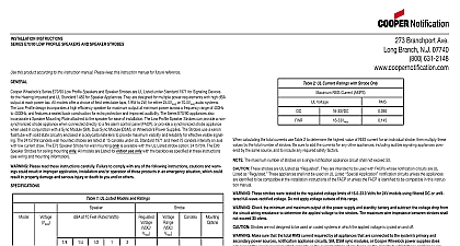
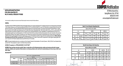
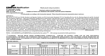
INSTALLATION INSTRUCTIONS E70H E90H HIGH FIDELITY SPEAKERS this product according to this instruction manual Please keep this instruc manual for future reference Wheelock Series E70H E90H High Fidelity Low Profile Speakers are UL under UL Standard 1480 for Speaker Appliances and ULC Listed under CAN ULC S541 07 for Speaker Appliances They are designed for power requirements with high dBA output at each power tap All mod offer a choice of field selectable taps 1 8W to 2W for either 25.0 VRMS or VRMS audio systems The Low Profile design incorporates a high efficiency for maximum output at minimum power across a frequency range 300 8000Hz The Series E70H 90 appliances also incorporate a Speaker Plate attached to the speaker for ease of installation All models Listed for indoor use only with the backboxes specified in these instruc see wiring and mounting information 1 8W tap setting for Private only E70H E90H series speakers are UL rated to meet the NFPA 72 for 520Hz signals in sleeping areas when used in conjunction Wheelock Safepath products see SP40S manual for more details All Canadian Installations should be in accordance with the Canadian for the Installation of Fire Alarm Systems CAN ULC S524 01 and Electrical Code Part 1 Final acceptance is subject to Authorities Jurisdiction The speaker appliance is a alarm device do not paint Please read these instructions carefully Failure to comply with of the following instructions cautions and warnings could result in application installation and or operation of these products in an situation which could result in property damage and serious or death to you and or others 1A UL Listed Models and Ratings at 10 Feet Watts 1B ULC Listed Models and Ratings dBA Per Rated Watts 2 ULC Directional Characteristics 19 degrees horizontal 35 degrees vertical 40 degrees horizontal 45 degrees vertical Models are Listed for indoor use with a temperature range of 32 to 0 to 49 and maximum humidity of 93 RH The effect of and storage temperatures shall not adversely affect the perfor of the appliance when it is stored in the original cartons and is not to misuse or abuse The maximum supervision voltage is 33 volts DC Frequency range of speakers is 300 8000Hz Always operate audio amplifiers and speakers within their speci ratings Excessive input may distort sound quality and may damage equipment Do not exceed 100 of speaker input voltage per UL 1480 input voltage can damage speaker If distortion is heard check for of the audio appliance with an oscilloscope and reduce the amplifier level or gain level to eliminate any clipping AND MOUNTING INFORMATION The following figures show the maximum number of field wires that can enter the backbox used with each mounting option If limits are exceeded there may be insufficient space in the backbox to the field wires and stresses from the wires could damage the Check that the installed product will have sufficient clearance and room prior to installing backboxes and conduit especially if sheathed cable or 3 4 inch 1.9 cm conduit fittings are used the limits shown for each mounting option comply with the National Code NEC Cooper Notification recommends use of the largest option shown and the use of approved stranded field wires whenever to provide additional wiring room for easy installation and minimum on the product from wiring Surface backbox SBB in Figure B is compatible with wiremold and mounting holes are for single gang double gang 4 inch 10.16 cm 10.16 cm 3 1 2 inch 8.9 cm and 4 inch 10.16 cm octagon or round MOUNTING SPEAKER MOUNTING SPEAKER SQ X 1 1 2 RING SQ X 2 1 8 OR GRILLE NUMBER OF CONDUCTORS 18 AWG 16 AWG 14 AWG 12 4 4 4 18 AWG 16 AWG 14 AWG 12 NUMBER OF CONDUCTORS 4 4 4 E90H has a round grille E70H is shown This model has in out wiring terminals that accept two 12 to 18 American Gauge AWG wires at each screw terminal Strip leads 3 8 inches 96 and connect to screw terminals Break all in out wire runs on supervised circuits to ensure integrity of circuit as shown in Figure 1 The polarity shown in the wiring diagrams for operation of the appliances 1 2 Connect ground wire to backbox Install signaling appliance to using mounting screws provided Branchport Ave Long Branch N J 07740 800 631 2148 www coopernotification comPN P85326BCopyright 2015 Cooper Wheelock Inc dba Cooper Notificationfirealarmresources com Check electrical ratings specified in tables 1 and 2 as ap to ensure proper input Check to ensure that wiring at facp is Improper electrical input can damage the product or cause it to which could result in property damage and serious injury or to you and or others B C D E F GH A B C D E F G H 3 Jumper plug is used to tap settings dBA loudness 4 Tap Settings setting is 70V 1 2W Tap F Each doubling of rated Watts increases sound output by 3 dBA Field input terminals are provided on each unit The following wattage are available 1 8W 1 4W 1 2W 1W and 2W Each letter corresponds to a plug position of the header located on the circuit board Select voltage and wattage as shown in Table 3 A 1.5 blocking capacitor for DC supervision of audio lines by the FACP factory wired in series with the speaker input Use needle nose pliers to pull and properly insert the jumper plug to desired tap setting 3 Speaker Voltage and Wattage Connection Chart PROCEDURES These models can be flush mounted to a 4 inch 10.16 square by 2 1 8 5.52 cm deep backbox with a 4 inch 10.16 cm sq 1 1 2 inch extension ring Figure A or surface mounted to a surface back Figure B Mounting hardware for each mounting option is supplied Conduit entrances to the backbox should be selected to provide sufficient clearance for the installed product Do not pass additional wires for other than the signaling appliance through the backbox Such wires could result in insufficient wiring space for the signaling When terminating field wires do not use more lead length than required lead length could result in insufficient wiring space for the signaling Use care and proper techniques to position the field wires in the backbox that they use minimum space and produce minimum stress on the This is especially important for stiff heavy gauge wires and wires thick insulation or sheathing These models have an integrated speaker mounting plate which must be correctly when it is mounted to the backbox Turn the speaker plate so that the arrows above the word point to the top of the speaker mounting plate Mount the speaker mounting plate to the backbox Next slide the grille the speaker mounting plate and attach with 2 screws The E70H E90H speaker appliance is a alarm device do paint this appliance is required to produce a distinctive three pulse Temporal Fire Alarm Evacuation Signal for total evacuation in accordance NFPA 72 the appliance must be used with a fire alarm control unit that generate the temporal pattern signal Refer to manufacturer installation for details Check the installation instructions of the manufacturers of other used in the system for any guidelines or restrictions on wiring and locating Notification Appliance Circuits NAC and notification appliances system communication circuits and or audio circuits for example may special precautions to ensure electrical noise immunity e g audio This device complies with part 15 of the FCC Rules Operation is to the following two conditions 1 This device may not cause harmful