Wheelock Eluxa low frequency sounder wall install sheet P85753

File Preview
Click below to download for free
Click below to download for free
File Data
| Name | wheelock-eluxa-low-frequency-sounder-wall-install-sheet-p85753-3450792681.pdf |
|---|---|
| Type | |
| Size | 1.98 MB |
| Downloads |
Text Preview
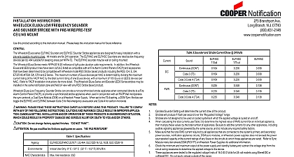
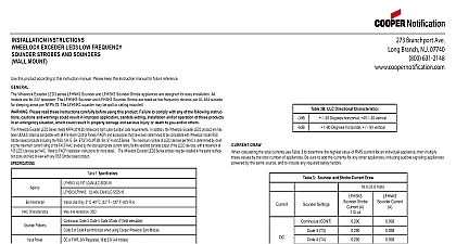
INSTALLATION INSTRUCTIONS ELUXA LOW FREQUENCY SOUNDER SOUNDER STROBE WITH PRE WIRE PRE TEST MOUNT this product according to this instruction manual Please keep this instruction manual for future reference Wheelock Eluxa series ELFHN Sounder 520Hz and ELFHS Sounder Strobe 110 177cd appliances are designed for easy with a pre wire capable mounting plate All models are for 24V operation The ELFHN Sounder and ELFHS Sounder are rated as low frequency devices per UL 464 suitable for sleeping areas per NFPA 72 The ELFHN sounder may be wall or mounted Wheelock Eluxa Series meets NFPA 2016 20 millisecond light pulse duration code requirements In addition the Wheelock and LED3 product lines have been UL ULC listed as compatible with all Fire Alarm Control Panels FACP and accessories have been determined to be compatible with Wheelock model RSS Strobe based products including the RSS CH E EH SA STH and Z Series The maximum number of Eluxa devices per NAC is determined by dividing the maximum rating of the FACP NAC by the total current rating of one Eluxa device with a maximum of 105 Eluxa or LED3 devices per Refer to FACP installation instructions for more detail The Wheelock Eluxa Series and Exceder LED3 Series strobes may be in the same notification zone and field of view with any RSS Strobe based product Eluxa Low Frequency Sounder Strobe can provide a non synchronized strobe appliance when connected directly to a Fire Control Panel FACP or provide a synchronized strobe appliance when used in conjunction with an FACP that incorporates sync protocol a Dual Sync Module DSM or a Wheelock Power Supply When set to the T3 4 setting a DSM Sync Module can the ELFHS and ELFHN between Code 3 for fire emergency evacuation and Code 4 for carbon monoxide PLEASE READ THESE INSTRUCTIONS CAREFULLY BEFORE USING THIS PRODUCT FAILURE TO COMPLY ANY OF THE FOLLOWING INSTRUCTIONS CAUTIONS AND WARNINGS COULD RESULT IN IMPROPER APPLICA CANDELA SETTING INSTALLATION AND OR OPERATION OF THESE PRODUCTS IN AN EMERGENCY SITUATION COULD RESULT IN PROPERTY DAMAGE AND SERIOUS INJURY OR DEATH TO YOU AND OR OTHERS Do not change factory applied finishes NOT PAINT Ne pas modifiez les finitions appliqu en usine PAS PEINTURER 1 Specifications UL 464 ULC 525 16 UL 1638 ULC S526 16 Use Only 0 C 50 C 32 F 122 F 93 R H Characteristics line resistance 35 Continuous Code 3 field selectable Patterns Sync Protocol Code 3 Sync Code 4 or T3 T4 Sync Selectable with DSM Operation Use Countinuos Setting on ELFHN Sounder Only Model Voltage or FWR 24V Regulated 16 to 33V All models Candela or 177 cd field selectable 2a ELFHS and ELFHN dBA Sound Output 24 Volts dBA at 10 Feet per UL 464 dBA at 10 Feet per ULC S525 16 3 3 Code 4 2b ULC Directional Characteristics 80 Degrees horizontal 80 vertical 90 Degrees horizontal 90 vertical The Code 3 temporal pattern 1 2 second on 1 2 second off 1 2 second on 1 2 second off 1 2 second on 1 1 2 off and repeat specified by ANSI and NFPA 72 for standard emergency evacuation signaling Available with Sync or Non Sync operation The Code 4 temporal pattern 100 ms on followed by 100 ms off for 4 cycles followed by 5 seconds of silence and repeat specified by ANSI and NFPA 720 for carbon monoxide emergency signaling Available with Sync operation only Code 4 T4 not synchronize on multi NAC multi zone installations To improve synchronization NAC must be energized simultaneously 3 Sounder and Strobe Current Draw 24 Volts CONT 3 T3 3 Code 4 T3 4 CONT 3 T3 3 Code 4 T3 4 cd Setting will determine the current draw of the product will produce 1 flash per second over the Voltage range are not designed to be used on coded systems in which the applied voltage is cycled on and off calculating the total currents use Table 3 to determine the highest value of RMS current for an individual appliance then these values by the total number of appliances Be sure to add the currents for any other appliances including audible appliances powered by the same source and to include any required safety factors sure that the total RMS current required by all appliances that are connected to the system primary and secondary sources notification appliance circuits DSM sync modules or Wheelock power supplies does not exceed the power capacity or the current ratings of any fuses on the circuits to which these appliances are wired Refer to Sync instruction sheets DSM P83177 or Wheelock Power Supplies for additional information the minimum and maximum output of the power supply and standby battery and subtract the voltage drop from the wiring resistance to determine the applied voltage to the device appliances were tested to the regulated voltage limits of 16.0 33.0 Volts for 24 volt models using filtered DC or unfiltered Do not apply voltage outside of this range notification appliances are UL Listed as They are intended to be used with Fire Alarm Control Panels whose notification circuits are UL Listed as Refer to the FACP instructions or the Wheelock Strobe Data Sheet P85328 for special application and strobe synchronization compatibility When using Sounder Only on a FACP Listed as Special Application do not exceed 85 of Maximum NAC current Rating OVERLOADING POWER SOURCES OR EXCEEDING FUSE RATINGS COULD RESULT IN LOSS OF POWER FAILURE TO ALERT OCCUPANTS DURING AN EMERGENCY WHICH COULD RESULT IN PROPERTY DAMAGE AND INJURY OR DEATH TO YOU AND OR OTHERS NFPA 72 ANSI 117.1 conform to ADAAG Equivalent Facilitation Guidelines in using fewer higher intensity strobes within the protected area WHEN INSTALLING STROBES IN AN OPEN OFFICE OR OTHER AREAS CONTAINING PARTITIONS OR OTHER OBSTRUCTIONS SPECIAL ATTENTION SHOULD BE GIVEN TO THE LOCATION OF THE STROBES SO THAT OPERATING EFFECT CAN BE SEEN BY ALL INTENDED VIEWERS WITH THE INTENSITY NUMBER AND TYPE OF BEING SUFFICIENT TO MAKE SURE THAT THE INTENDED VIEWER IS ALERTED BY PROPER ILLUMINATION OF THE VIEWER ORIENTATION A SMALL POSSIBILITY EXISTS THAT THE USE OF MULTIPLE STROBES WITHIN A PERSON FIELD OF VIEW CERTAIN CIRCUMSTANCES MIGHT INDUCE A PHOTO SENSITIVE RESPONSE IN PERSONS WITH EPILEPSY REFLECTIONS IN A GLASS OR MIRRORED SURFACE MIGHT ALSO INDUCE SUCH A RESPONSE TO MINIMIZE POSSIBLE HAZARD COOPER WHEELOCK STRONGLY RECOMMENDS THAT THE STROBES INSTALLED SHOULD PRESENT A COMPOSITE FLASH RATE IN THE FIELD OF VIEW WHICH EXCEEDS FIVE 5 HZ AT THE OPERAT VOLTAGE OF THE STROBES COOPER WHEELOCK ALSO STRONGLY RECOMMENDS THAT THE INTENSITY AND FLASH RATE OF INSTALLED STROBES COMPLY WITH LEVELS ESTABLISHED BY APPLICABLE LAWS REGULATIONS CODES AND GUIDELINES Check the installation instructions of the manufacturers of other equipment used in the system for any or restrictions on wiring and or locating Notification Appliance Circuits NAC and notification appliances Some communication circuits and or audio circuits for example may require special precautions to assure immunity from noise e g audio crosstalk P85753A273 Branchport Ave Long Branch N J 07740 800 631 2148 www coopernotification comCopyright 2020 Cooper Wheelock Inc dba Cooper Notification All rights reserved 1firealarmresources com SETTINGS AND MOUNTING All Eluxa horn strobe appliances have terminals that accept 12 to 18 American Wire Gauge AWG wires at each screw terminal leads 3 8 inches and connect to screw terminals Do not fully back out terminal screws Break all in out wire runs on supervised circuits to ensure integrity of circuit supervision as shown in Figure 3 The polarity shown in 2 the wiring diagram is for the operation of the appliances The polarity is reversed by the FACP during supervision T3 T4 Sync Selectable operation requires a DSM 12 24 Refer to DSM P83177 instructions All appliances must be set to T3 T4 4 T4 operation occurs when both Strobe NAC and Audible NAC remain active Code 3 T3 operation occurs when Strobe is active and Audible NAC is not acttive Audible Silence function is available only when using Continuos or T3 setting The Notification Appliance Circuits NAC to DSM must be continuous DC in Alarm Inputs to DSM may not be syn