Wheelock Eluxa speaker ceiling install sheet P85758

File Preview
Click below to download for free
Click below to download for free
File Data
| Name | wheelock-eluxa-speaker-ceiling-install-sheet-p85758-8543912076.pdf |
|---|---|
| Type | |
| Size | 1.86 MB |
| Downloads |
Text Preview
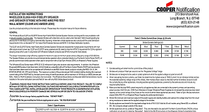
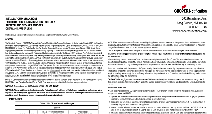
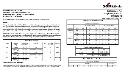
INSTALLATION INSTRUCTIONS ELUXA HIGH FIDELITY SPEAKER SPEAKER STROBES WITH PRE WIRE PRE TEST MOUNT CLEAR AND AMBER LENS this product according to this instruction manual Please keep this instruction manual for future reference Wheelock Eluxa ELSPC and ELSPSTC Series High Fidelity Multi Candela Speaker Strobes are designed for easy installation with pre wire capable mounting plate The Speaker Strobes with Amber lens are for Private Mode Emergency General Utility Signaling lens strobe appliances also comply with the polar distribution requirements in the UL Standard 1971 for Indoor Fire Protection and NFPA 72 for Mass Notification Systems and ELSPSTC series High Fidelity Multi Candela Speakers Strobes are designed for multiple power requirements with high dBA at each power tap ELSPC and ELSPSTC series Speakers are UL rated to meet the NFPA 72 requirement for 520Hz signals in areas when used in conjunction with Wheelock Safepath products see SP40S manual for more details design incorporates a high efficiency speaker for maximum output at minimum power across a frequency range of 300 8000Hz strobes can provide non synchronized strobe operation when connected directly to a Fire Alarm Control Panel FACP or provide strobe operation when used in conjunction with a Dual Sync Module DSM or Wheelock Power Supplies Wheelock Eluxa Series meets NFPA 2016 20 millisecond light pulse duration code requirements In addition the Wheelock Eluxa LED3 product lines have been UL ULC listed as compatible with all Fire Alarm Control Panels FACP and accessories that have determined to be compatible with Wheelock model RSS Strobe based products including the RSS CH E EH ET ST HS MT S8 STH and Z Series The maximum number of Eluxa devices per NAC is determined by dividing the maximum current rating of the NAC by the total current rating of one Eluxa device with a maximum of 105 Eluxa or LED3 devices per NAC Refer to FACP instructions for more detail The Wheelock Eluxa Series and Exceder LED3 Series strobes may be installed in the same zone and field of view with any RSS Strobe based product PLEASE READ THESE INSTRUCTIONS CAREFULLY BEFORE USING THIS PRODUCT FAILURE TO COMPLY ANY OF THE FOLLOWING INSTRUCTIONS CAUTIONS AND WARNINGS COULD RESULT IN IMPROPER APPLICA CANDELA SETTING INSTALLATION AND OR OPERATION OF THESE PRODUCTS IN AN EMERGENCY SITUATION COULD RESULT IN PROPERTY DAMAGE AND SERIOUS INJURY OR DEATH TO YOU AND OR OTHERS Do not change factory applied finishes NOT PAINT Ne pas modifiez les finitions appliqu en usine PAS PEINTURER UL1971 ULC 526 16 ELSPSTC A UL1638 ULC 526 16 1 Specifications UL1480 ULC 541 16 Use Only 32 to 122 0 to 50 93 RH Characteristics line resistance 35 Voltage 25Vrms or 70.7Vrms DC or FWR 24V Regulated 16 to 33V 15 30 75 110 150 177cd field selectable 1 8W 1 4W 1 2W 1W 2W 5W field selectable is an on axis rating where the following applies effective candela rating per UL1971 2a UL ULC Listed Speaker Models and Ratings dBA at 10 Feet Per UL 1480 dBA at 10 Feet ULC S541 16 2b ULC Directional Characteristics 80 degrees horizontal 80 degrees vertical 90 degrees horizontal 90 degrees vertical 3 Strobe Current Draw Amps 24 volts Candela Settings cd Candela setting will determine the current draw of the product Strobes will produce 1 flash per second over the Voltage range Strobes are not designed to be used on coded systems in which the applied voltage is cycled on and off When calculating the total currents use Table 3 to determine the highest value of Current for an individual strobe across expected operating voltage range of the strobe then multiply these values by the total number of strobes be sure to add currents for any other appliances including audible signaling appliances powered by the same source and include any safety factors Make sure that the total RMS current required by all appliances that are connected to the system primary and secondary sources NAC Circuits DSM Sync Modules or Cooper Wheelock Power Supplies do not exceed the power sources rated or the current ratings of any fuses on the circuits to which these appliances are wired Refer to Sync Module instruction DSM P83177 or Wheelock Power Supplies for additional information Check the minimum and maximum output of the power supply and standby battery and subtract the voltage drop from the circuit resistance to determine the applied voltage to the strobes Strobe appliance was tested to the regulated voltage limits of 16.0 33.0 Volts for 24 volt models using filtered DC or unfiltered Do not apply voltage outside of this range Strobe appliances are UL Listed as They are intended to be used with Fire Alarm Control Panels FACPs whose circuits are UL Listed as Refer to the FACP instructions or the Wheelock Strobe Compatibility Data P85328 for special application and strobe synchronization compatibility AMBER STROBES ARE NOT TO BE USED AS A VISUAL PUBLIC MODE ALARM NOTIFICATION APPLIANCE OVERLOADING POWER SOURCES OR EXCEEDING FUSE RATINGS COULD RESULT IN LOSS OF POWER FAILURE TO ALERT OCCUPANTS DURING AN EMERGENCY Always operate audio amplifiers and speakers within their specified ratings Excessive input may distort quality and may damage audio equipment Improper input voltage can damage speaker If distortion is heard check clipping of the audio signal voltage with an oscilloscope and reduce the amplifier input level or gain level to eliminate clipping WHEN INSTALLING STROBES IN AN OPEN OFFICE OR OTHER AREAS CONTAINING PARTITIONS OR OTHER OBSTRUCTIONS SPECIAL ATTENTION SHOULD BE GIVEN TO THE LOCATION OF THE STROBES SO THAT OPERATING EFFECT CAN BE SEEN BY ALL INTENDED VIEWERS WITH THE INTESITY NUMBER AND ILLUMINA REGARDLESS OF THE VIEWER ORIENTATION A SMALL POSSIBILITY EXISTS THAT THE USE OF MULTIPLE STROBES WITHIN A PERSON FIELD OF UNDER CERTAIN CIRCUMSTANCES MIGHT INDUCE A PHOTO SENSITIVE RESPONSE IN PERSONS WITH EPILEPSY REFLECTIONS IN A GLASS OR MIRRORED SURFACE MIGHT ALSO INDUCE SUCH A RESPONSE TO MINIMIZE POSSIBLE HAZARD COOPER WHEELOCK STRONGLY RECOMMENDS THAT THE STROBES INSTALLED SHOULD PRESENT A COMPOSITE FLASH RATE IN THE FIELD OF VIEW WHICH EXCEEDS FIVE 5 HZ AT THE OPERAT VOLTAGE OF THE STROBES COOPER WHEELOCK ALSO STRONGLY RECOMMENDS THAT THE INTENSITY AND FLASH RATE OF INSTALLED STROBES COMPLY WITH LEVELS ESTABLISHED BY APPLICABLE LAWS REGULATIONS CODES AND GUIDELINES NFPA 72 ANSI 117.1 conforms to ADAAG Equivalent Facilitation Guidelines in using fewer higher intensity strobes within the protected area Branchport Ave Long Branch N J 07740 800 631 2148 www coopernotification comP85758BCopyright 2020 Cooper Wheelock Inc dba Cooper Notification All rights reserved firealarmresources com INFORMATION blocking capacitor for DC supervision of audio lines by the FACP is factory wired in series with the speaker input Supervision voltage not exceed 33 volts DC ELSPST Speaker Strobe models have terminals that accept 12 to 18 American Wire Gauge AWG wires at each screw terminal leads 3 8 inches and connect to screw terminals Do not fully back out terminal screws Break all in out wire runs on supervised circuits to assure integrity of circuit supervision as shown in Figure 2 The polarity shown in 1 the wiring diagram is for operation of the appliances Using the slide switch shown in Figure 3 select voltage and wattage as shown in Table 4 below Each letter corresponds to a position of switch located on the printed circuit board The ELSP comes pre set on setting F 70V 1 2 W Each doubling of rated Watts increases sound output by 3 dBA OPTIONS A Surface Mount with LSPKBB C B Flush Mount 4 x 2 1 8 Back Box SQUARE BACKBOX THREAD CUTTING SCREW THREAD CUTTING SCREW PRECEDING FACP SYNC MODULE PRECEDING NEXT SIGNAL END OF LINE EOLR