Wheelock ET70WP weatherproof speaker strobe install sheet P84848

File Preview
Click below to download for free
Click below to download for free
File Data
| Name | wheelock-et70wp-weatherproof-speaker-strobe-install-sheet-p84848-2345069781.pdf |
|---|---|
| Type | |
| Size | 933.83 KB |
| Downloads |
Text Preview
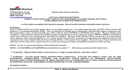
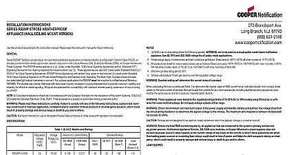
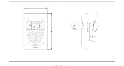
INSTALLATION INSTRUCTIONS ET70WP LOW PROFILE WEATHERPROOF STROBE APPLIANCE this product according to this instruction manual Please keep this instruction manual for future reference ET70WP Low Profile Speaker Strobe appliances are UL Listed for indoor outdoor use under Standard 1638 for Visual Signal Fire Protective Service and UL Standard 1480 for Speaker Appliances Models with amber blue green or red lenses are UL under Standard 1638 Visual Signaling Appliance for Private Mode Emergency and General Utility Signaling The ET70WP with lens is UL Listed to Standard 1971 for Signaling Devices for the Hearing Impaired when installed indoors For outdoor applications ET70WP must be mounted to a Weatherproof Backbox IOB The ET70WP is designed for multiple power requirements with high dBA at each power tap This model offers a choice of field selectable taps 1 8W to 8W for either 25.0VRMS or 70.0VRMS audio systems low profile design incorporates a high efficiency speaker for maximum output at minimum power across a frequency range of 400Hz 4000Hz and features a sealed back construction for extra protection and improved audibility The Low Profile Speaker Strobes can a non synchronized strobe appliance when connected directly to a fire alarm control panel FACP or provide a synchronized appliance when used in conjunction with a Sync Module SM Dual Sync Module DSM or Cooper Wheelock power supplies strobes use a Xenon flashtube with solid state circuitry enclosed in a polycarbonate lens to provide maximum visibility and reliability effective visible signaling Please read these instructions carefully Failure to comply with any of the following instructions cautions and warn could result in improper application installation and or operation of these products in an emergency situation which could in property damage and serious injury or death to you and or others Not recommended for use at refrigerator freezer door entrances or other areas with persistent condensations 1 UL Listed Models and Ratings dBA at 10 Feet Watts Strobe Candela cd 1 UL1638 is an on axis rating where the following applies WARNING not to be used as a visual public model alarm notification appli Use UL1971 ratings for all public mode applications All products are listed for indoor and outdoor use as follows Clear Lens at 40 F 40 C to 150 F 66 C Colored Lens at 31 F C both Clear and Colored Lens with maximum of 95 RH Strobes will produce 1 flash per second over the Regulated Voltage range Strobes with clear and amber lenses meet the required light distribution pattern in UL1971 The effect of shipping and storage temperatures must not adversely affect the performance of the appliance when it is stored in the cartons and is not subjected to misuse or abuse The maximum supervision voltage is 33 volts DC Frequency range of speakers is 400 4000Hz dBA is rated per UL Standard 1480 for Speaker Appliances Always operate audio amplifiers and speakers within their specified ratings Excessive input may distort sound quality and damage audio equipment Do not exceed 100 of speaker input voltage per UL 1480 Improper input voltage can damage speaker distortion is heard check for clipping of the audio appliance with an oscilloscope and reduce the amplifier input level or gain level to any clipping 2 Strobe Current Ratings AMPS RMS Current Voltage 2 calculating the total currents use Table 2 to determine the highest value of RMS current for an individual strobe then multiply these by the total number of strobes Add the currents for any other appliances including audible signaling appliances powered by the source and include any required safety factors The maximum number of strobes on a single notification appliance circuit must not exceed 50 These strobes are UL Listed as Regulated They are intended to be used with FACPs whose notification circuits are UL Listed Regulated These appliances must not be used on UL Listed Special Application notification circuits unless the appliances are identified be compatible in the installation instructions of the FACP These strobes were tested to the regulated voltage limits of 16 33 Volts for 24V models using filtered DC or unfiltered voltage Do not apply voltage outside of this range Check the minimum and maximum output of the power supply and standby battery and subtract the voltage drop the circuit wiring resistance to determine the applied voltage to the strobes The maximum wire impedance between strobes not exceed 35 ohms Strobes are not designed to be used on coded systems in which the applied voltage is cycled on and off Ensure the total RMS current required by all appliances that are connected to the system primary and second power sources notification appliance circuits SM DSM sync modules or Cooper Wheelock power supplies does not the power source rated capacity or the current ratings of any fuses on the circuits to which these appliances are wired power sources or exceeding fuse ratings could result in loss of power and failure to alert occupants during an emer which could result in property damage and serious injury or death to you and or others AND MOUNTING INFORMATION Figure 1 shows the maximum number of field wires conductors that can enter the backbox used with each mounting option these limits are exceeded there may be insufficient space in the backbox to accommodate the field wires and stresses from the wires damage the product This unit must be mounted on a flat surface with the surface covering the entire back surface of the backbox When used in an application or a NEMA 3R application knockouts in the rear of the backbox must remain intact Two screws must be used to mount backbox securely using both tabs included with the backbox the limits shown for each mounting option comply with the National Electrical Code NEC Cooper Wheelock recommends use the largest backbox option shown and the use of approved stranded field wires whenever possible to provide additional wiring room easy installation and minimum stress on the product from wiring Branchport Ave Long Branch N J 07740 800 631 2148 www coopernotification comPN P84848FCopyright 2012 Cooper Wheelock Inc dba Cooper Notificationfirealarmresources com STROBE COM 2 Figure 3 When installing strobes in an open office or other areas containing partitions or other viewing obstructions special should be given to the location of the strobes so that their operating effect can be seen by all intended viewers with the number and type of strobes being sufficient to ensure the intended viewer is alerted by proper illumination Failure to do could result in property damage and serious injury or death to you and or others PROCEDURES The knock out opening on the backbox is sized for a conduit and matching connector Ensure a proper watertight conduit fitting is to connect the backbox for outdoor severe environment applications Conduit entrances to the backbox should be selected to sufficient wiring clearance for the installed product Do not pass additional wires used for other than the signaling appliance the backbox Such additional wires could result in insufficient wiring space for the signaling appliance When terminating field wires do not use more lead length than required Excess lead length could result in insufficient wiring space the appliance Use care and