Wheelock Exceder ceiling install sheet P85066

File Preview
Click below to download for free
Click below to download for free
File Data
| Name | wheelock-exceder-ceiling-install-sheet-p85066-3984607251.pdf |
|---|---|
| Type | |
| Size | 1.35 MB |
| Downloads |
Text Preview
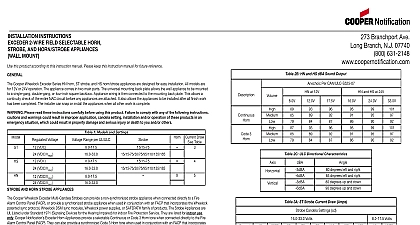
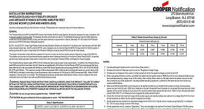
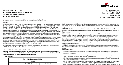
INSTALLATION INSTRUCTIONS EXCEDER SERIES 2 WIRE FIELD HORN STROBE AND HORN STROBE CEILING MOUNT this product according to this instruction manual Please keep this instruction manual for future reference Cooper Wheelock Exceder Series HN C Horn ST C Strobe and HS C Horn Strobe Appliances are designed for easy installation All models for 12V or 24V operation The appliance comes in two main parts The universal mounting back plate allows the the ceiling appliance to be to a single gang double gang 4 inch square 4 inch octagon or a 3 octagon backbox Two wire appliance wiring is then con to the mounting back plate This allows a continuity check of the entire NAC circuit before any appliances are attached It also allows the to be installed after all finish work has been completed The installer can snap or install the appliances when all other work is complete Please read these instructions carefully before using this product Failure to comply with any of the following instruc cautions and warnings could result in improper application candela setting installation and or operation of these products an emergency situation which could result in property damage and serious injury or death to you and or others 1 Models and Settings VDC VDC VRMS VDC VDC VRMS VDC VRMS VDC VRMS Range per UL ULC cd Draw Table AND HORN STROBE APPLIANCES Notification Exceder Multi Candela Strobes can provide a non synchronized strobe appliance when connected directly to a Fire Control Panel FACP or provide a synchronized strobe appliance when used in conjunction with an FACP that incorporates the sync protocol a Wheelock Sync Module or the Wheelock Power Supply The Strobe Appliances are UL Listed under Standard Signaling Devices for the Hearing Impaired for indoor Fire Protection Service They are listed for indoor use only Cooper Notifica Exceder Horn Appliances provide a selectable Continuous or Code 3 Horn tone when connected directly to the Fire Alarm Control FACP They can also provide a synchronized Code 3 Horn tone when used in conjunction with an FACP that incorporates the sync protocol a Wheelock Sync Module or the Wheelock Power Supply The Horn Appliances can be field set for High HI MED or Low LO dBA sound output The Horn Appliances are UL Listed under Standard 464 for Audible Signal Appliances are listed for indoor use only All models are designed for use with either filtered DC VDC or unfiltered Full Wave Rectified VRMS voltage All inputs are polarized for compatibility with standard reverse polarity supervision of circuit wiring by an FACP The ST C HS C Horn Strobe and the HN C Horn are for 12V or 24V operation Strobe devices for 12V are only approved by UL to be set at and only to be powered by DC not FWR The HN C may be used on both wall and ceiling applications The Code 3 temporal pattern 1 2 second on 1 2 second off 1 2 second on 1 2 second off 1 2 second on 1 1 2 off and repeat specified by ANSI and NFPA 72 for standard emergency evacuation signaling The Code 3 Horn should be used only for fire evacua signaling and not for any other purpose 2A HN C and HS C dBA Sound Output dBA Per UL 464 3 Horn and HS C at 12V and HS C at 24V Branchport Ave Branch N J 07740 631 2148 2B HN C and HS C dBA Sound Output Per CAN ULC S525 07 and HS C at 12V and HS C at 24V 3 Horn 2C ULC Directional Characteristics left and right left and right up and down up and down 3 ST C Strobe Current Draw Amps Candela Settings cd Volts Volts 4 HS C Horn Strobe Current Draw Amps Candela Settings cd Volts Current Draw is the same for the Continuous Horn and Code 3 Horn Settings 5 HN C Horn Current Draw Amps Settings Volts Volts P85066C 2012 Cooper Wheelock Inc dba Cooper Notification Current Draw is the same for the Continuous and Code 3 Horn Settings Candela setting horn setting and voltage will determine the current draw of the product calculating the total currents use Tables 3 5 to determine the highest value of RMS current for an individual appliance then multiply values by the total number of appliances Be sure to add the currents for any other appliances including audible signaling appli powered by the same source and to include any required safety factors The maximum number of strobes on a single notification appliance circuit shall not exceed 50 These notification appliances are UL Listed as They are intended to be used with FACPs whose notification circuits are Listed as These appliances shall not be used on UL Listed Application notification circuits unless the appliances are to be compatible in the installation instructions of the FACP or unless the FACP is identified to be compatible in this instruction manual These notification appliances are UL Listed as They are intended to be used with FACPs whose notification circuits UL Listed as These appliances shall not be used on UL Listed Application notification circuits unless the appli are identified to be compatible in the installation instructions of the FACP or unless the FACP is identified to be compatible in this manual These appliances were tested to the regulated voltage limits of 16.0 33.0 Volts for 24 volt models and 8.0 17.5 Volts for 12 volt models using dc for the 12 volt range and either filtered dc or unfiltered dc for the 24 volt range voltage Do not apply voltage outside of this range Check the minimum and maximum output of the power supply and standby battery and subtract the voltage drop from the circuit wir resistance to determine the applied voltage to the strobes The maximum wire impedance between strobes shall not exceed 35 ohms Strobes are not designed to be used on coded systems in which the applied voltage is cycled on and off Make sure that the total RMS current required by all appliances that are connected to the system primary and secondary power notification appliance circuits DSM sync modules or Cooper Wheelock power supplies does not exceed the power sources capacity or the current ratings of any fuses on the circuits to which these appliances are wired Overloading power sources or fuse ratings could result in loss of power and failure to alert occupants during an emergency which could result in property and serious injury or death to you and or others SELECTION SELECTION WINDOW Candela factory settings are shown in above illustrations 4 Selector Switch Check that the installed product will have sufficient clearance and wiring room prior to installing backboxes and conduit espe if sheathed multi conductor cable